Chapter 4 - System Setup Installing the Breathing System and Flow Sensors
40 Apollo Operator’s Manual
Part Number: 90 38 237, 6th edition
When Apollo Is Not in Use
Observe the following if the Apollo is not used for an
extended period of time:
• Unplug the gas pipeline hoses from the wall
central gas supply.
• Close the cylinder valves on the backup gas
cylinders.
• Leave the workstation connected to the mains
at all times. The green LED labeled
>
N AC Power< lights up (1 in Figure 18).
Installing the Breathing System
and Flow Sensors
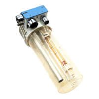
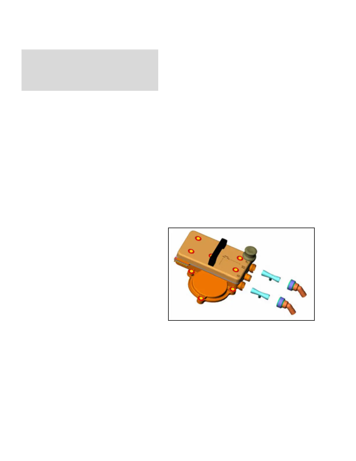
Figure 19. Installing the Flow Sensors1. Press the release button on the ventilator unit
and pull it out.
2. Loosen the three sealing screws on the ventilator
(1 in Figure 19) a quarter turn counterclockwise
with the wrench supplied.
3. Pull the breathing system up and out by the
handle (2 in Figure 19).
4. Insert the flow sensors (3 in Figure 19) into the
two port connections on the breathing system,
with the electric connection on each sensor
facing down in the slot.
Note: Flow sensors must be recalibrated after
replacement by performing the power-on
self test (see Chapter 5).
WARNING !
The battery must be charged at least every four
weeks. Allowing it to run low can lead to
damage.
3
3
4
4
1
1
1
2