Volume-Controlled Ventilation Chapter 7 - Ventilation
Apollo Operator’s Manual 89
Part Number: 90 38 237, 6th edition
Volume-Controlled Ventilation
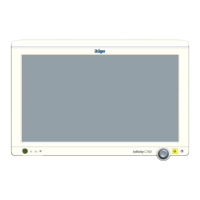
Figure 63. Respiratory Cycle - Volume ModeThe Apollo has a volume-controlled ventilation mode
with fixed mandatory tidal volume (V
T) and frequency
(Freq). Synchronization can be activated, as well as
variable pressure support for spontaneous breathing
efforts (optional).
The respiratory cycle (see Figure 63) is defined
through the frequency (Freq), the inspiratory time
(T
INSP), the magnitude of the inspiration flow, the
inspiratory pause time (T
IP:TINSP) and the tidal
volume (V
T). Synchronization and pressure support
are controlled by the sensitivity of the flow trigger and
the level of ∆P
PS. The maximum time interval for
controlled ventilation is set via the frequency. In order
to maintain a constant frequency, a time interval
triggered prematurely is compensated in the next
cycle.
Compliance Compensation
Ventilator compliance compensation is continuously
applied during volume-controlled ventilation so that
the tidal volume delivered to the patient corresponds
to the Vt setting. Ventilator compliance is determined
during the leak test performed in Standby mode. To
have compliance compensation work accurately, it is
important that the patient hoses used during the leak
test match the type of hoses used during the proce-
dure.
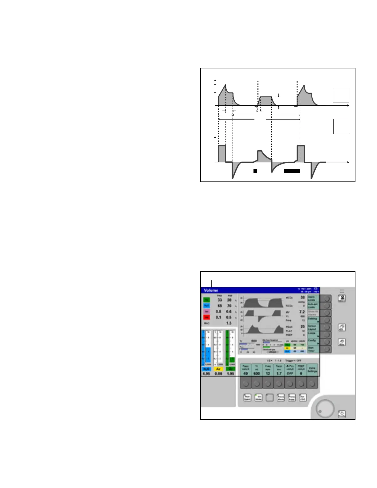
Figure 64. Volume Mode ScreenNote: When the ventilator settings for volume
mode cause the ventilator to operate at its
limits of performance, it is not possible for
the Apollo to apply compliance
compensation. If the ventilator's performance
limit is reached, it is not possible to
increment the Vt setting using the Vt soft key.
Starting Volume-Controlled Ventilation
Presetting the Volume Ventilation Mode
Prior to activating volume mode, the user can preset
the volume mode parameters.
1. Press the >Vol Mode< key located at the bottom
of the display panel (1 in Figure 64). The LED on
the key and the status field at the top of the
screen (2 in Figure 64) flash on and off.
The row of soft keys for the ventilation
parameters valid for volume mode are displayed
on a gray background (3 in Figure 64). This
means that they are not yet active.
Pressure
Time [s]
Flow
T
INSP
T
EXP
Time [s]
1/Freq.
P
MAX
P
PEAK
P
PLAT
T
IP
Trigger
on
Trigger indicator
P
PS
on
Flow-trigger window
Trigger indicator
T
SLOPE
P
PS
Flow trigger
25%
1
3
4
2