Description of the system
file:///D|/Manuales/Para%20recolocar/MOTOS/DUCATI/DUCATI/M796/wsm/EN/M796_ABS_11_6_10.33.1.html[11/12/2015 18:40:25]
Siemens M3C injection-ignition system
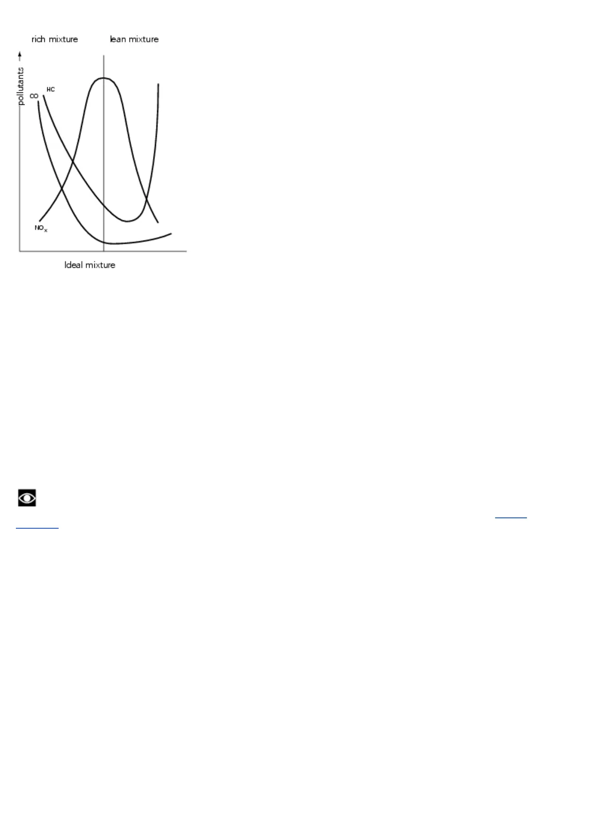
The Siemens M3C injection-ignition system is the Alfa/N type, in which the engine speed and throttle position are used as
main parameters for measuring the quantity of intake air. If the quantity of air is known, the quantity of fuel can be dosed
accordingly to obtain the required ratio. Other sensors in the system (engine sensor, intake air pressure, air temperature,
engine temperature and lambda sensor for CO control) allow corrections to the basic management strategy to suit specific
operating conditions. The engine speed and the throttle angle also make it possible to calculate the optimal advance for all
types of operating conditions. The quantity of air taken in by each cylinder during each cycle depends on the density of
the air in the intake manifold, the cylinder capacity and the volumetric efficiency.
Volumetric efficiency is experimentally taken onto the engine in the whole operating range (rotation speed and engine
load conditions). Taken values are then used for the generation of a map which is stored into the Flash Eprom of the
Siemens M3C ECU, for injection control. The Flash Eprom can be programmed via CAN line. Fuel injection control is of
the phased sequential type, i.e. the injectors are not operated in parallel. Fuel delivery to each cylinder can be started
from the expansion stage up to the intake stage, already in progress. Fuel cut-off timing (the time when the injectors are
closed), is saved in a special map, which is stored in the ECU Flash Eprom. Ignition is of the static inductive discharge
type, featuring dwell time control so as to ensure coil charging at steady power. The power modules for the coil power
supply are incorporated in the ECU hardware, while ignition advance curves are always stored in the Flash Eprom. Both
coils and power modules are controlled by the ECU, which processes ignition advance.
Note
To check the injection-ignition system components and wiring use the “DDS” tester, as explained under “Guided
diagnosis” (Sect. 6 - 13).
Sensor positioning diagram
1 Injection control unit
2 Injection relay
3 Fuel pump
4 Lambda sensor (horizontal cylinder)
5 Engine temperature sensor
6 Air temperature sensor
7 Coil (horizontal cylinder)
8 Pressure sensor
9 Engine rpm sensor
10 Coil (vertical cylinder)
11 Spark plug
12 Throttle position sensor
13 Injectors
14 Stepper motor
15 Lambda sensor (vertical cylinder)