System components
file:///D|/Manuales/Para%20recolocar/MOTOS/DUCATI/DUCATI/M796/wsm/EN/M796_ABS_11_6_12.35.1.html[11/12/2015 18:40:26]
The typical change in signal intensity occurs when the air-fuel ratio is 14.7 to 1 (14.7 parts of air to 1 part of petrol),
which is referred to as “Lambda 1”. This ratio is considered to be an indication of complete combustion, hence the name
“Lambda Sensor”: thus
lambda = 1 means mixture in stoichiometric (ideal) ratio
lambda >1 means a lean mixture
lambda <1 means a rich mixture.
The air-fuel ratio control system is managed by the lambda sensor, which starts to operate at over 300 °C: the ceramic
material starts conducting oxygen ions at around 300 °C. If the proportion of oxygen starts to differ between the two ends
of the probe, this generates an electrical voltage between the two electrodes due to the particular nature of the material.
This makes it possible to measure the difference in oxygen content between the exhaust gas and the ambient air.
Combusted gas still contains a residual amount of oxygen when the air-fuel mixture delivered to the combustion chamber
is incorrect. This makes it possible to adjust the injection control unit to ensure the engine always runs with the optimal
air-fuel ratio.
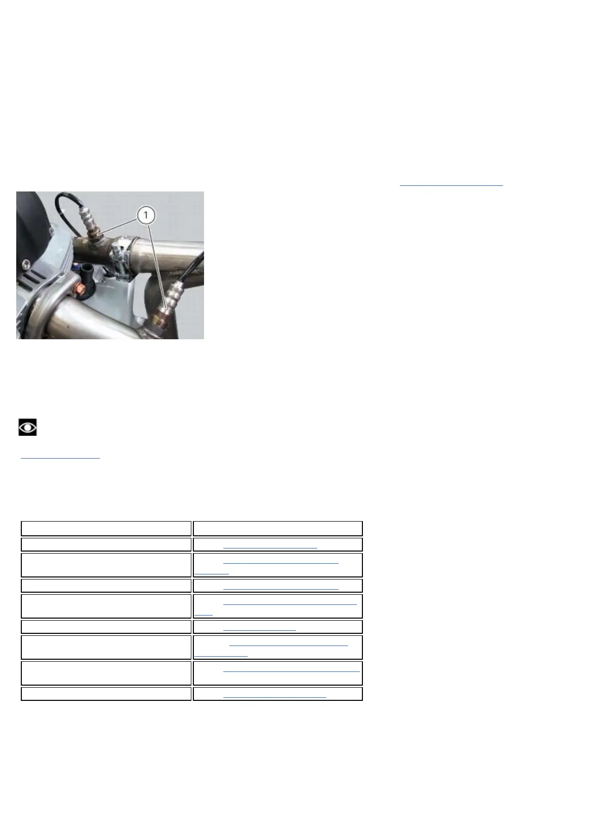
To remove the lambda sensors (1) it is necessary to unscrew them from the horizontal and vertical cylinder exhaust pipe.
When reassembling, tighten the sensors to a torque of 45 Nm ±10% (Sect. 3 - 3,
Frame torque settings).
Air pressure sensor
This sensor is powered by the ECU and it supplies information concerning the absolute air pressure in an area of the
motorcycle that is not subject to turbulence. The electronic signals thus obtained are transmitted to the ECU, where they
are used to make corrections in accordance with the detected pressure.
Note
To test the operation of the injector, use the DDS diagnosis instrument and follow the instructions given in the paragraph
“
Guided diagnosis” (Sect. 6 - 13).
Removing the air pressure sensor
To remove the air pressure sensor (1), remove the following parts.
Operations Section reference
Remove the seat 5 - 3, Removal of the seat
Remove the tank covers 5 - 2,
Removal of the fuel tank
fairings
Remove the fuel tank 8 - 2,
Removal of the fuel tank
Remove the ABS control unit 7 - 6,
Removing of the ABS control
unit
Remove the battery 6 - 2,
Battery support
Remove the ECU connector 6 - 12,
Removal of the electronic
control unit
Connect the starter motor/solenoid
cable
6 - 3,
Removal of the starter motor
Remove the airbox 8 - 7,
Removal of the airbox
Disconnect the main wiring connector (3) from the sensor and detach it from the throttle body.
Remove the tubes (2) from the intake manifolds.




 To Next Page