169
z Exterior
chap.3
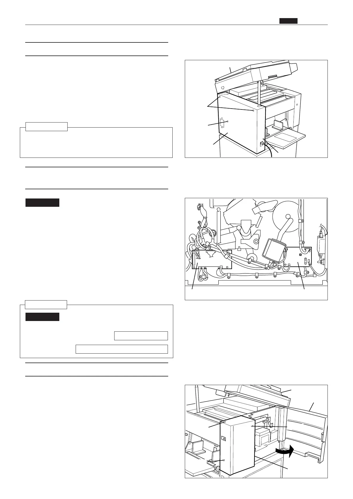
(5) Removal of Rear Cover
Scanner unit
Screws
Screw
Screw
Screw
Screw
Screw
Rear cover
Scanner unit
Front cover
Left front cover
Drive PCB unit Main motor PCB unit
1) Press the power switch to turn it off, then discon-
nect the power cord from the outlet.
2) Disconnect the power cord from the machine
body.
3) Open out the scanner unit.
4) Remove the 4 screws indicated, then remove the
rear cover.
: Always turn off the power before
replacing a PCB Unit.
1) Remove the rear cover. (See above for procedure.)
2) Remove the connectors of.
¡ Drive PCB Unit (8 connectors)
¡ Main motor PCB Unit (4 connectors)
3) Remove the mounting screws, and replace the
PCB units.
¡ Drive PCB Unit: 4 screws
¡ Main motor PCB Unit: 4 screws
IMPORTANT
1) Open the front covers and scanner unit.
2) Remove the 3 screws, then remove the left front
cover.
: After replacing Motor PCB Unit, per-
form readjustment.
IMPORTANT
(7) Removal of Left Front Cover
Reinstallation
HELP mode H-01 \ see p.295
¡ Reinstall the rear cover from the paper feed
side.
Reinstallation
63S00301
(6) Removal of Drive PCB Unit and Main
Motor PCB Unit
63S00365
63S00302
\See page 246