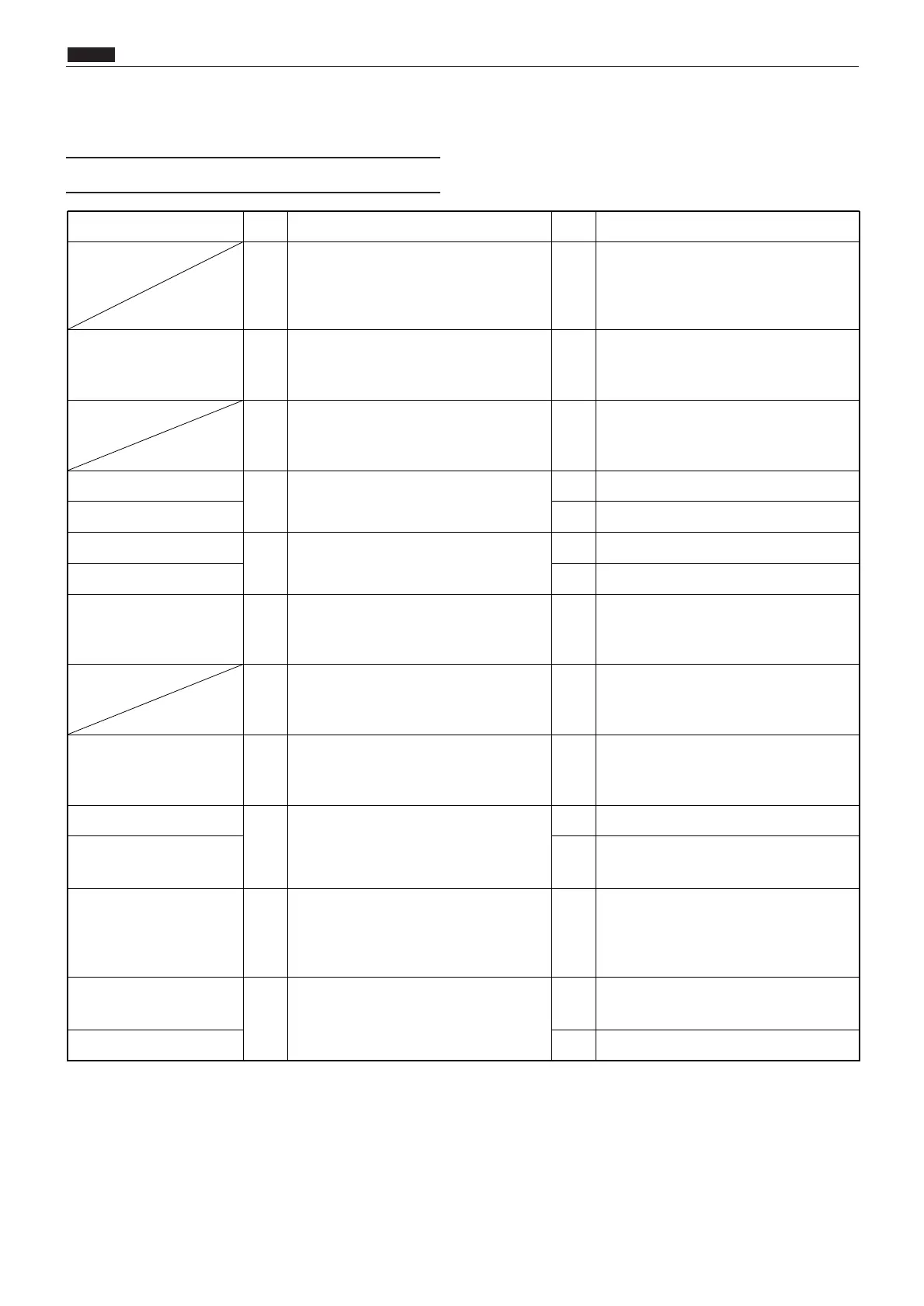
Cause/Detective section
Procedures
Result
CountermeasureItems to be checked
1
Measure the voltage between the regu-
lated power supply, CN2-1 (+) and
CN3-21(GND) with the tester. Is it
+24V?
No. Follow the procedure (6).
Drive PCB Unit 2
Measure the drive PCB unit CN3-19 (+)
and CN2-2(GND) with the tester. Is it
+24V?
No Replace the drive PCB Unit.
3
Does the lamp light up when the drive
PCB unit CN3-20 produces a short cir-
cuit to GND?
Yes Follow the procedure (5).
Lamp
4
Is the cause cleared by replacing the
lamp?
Yes Finish
Inverter PCB Unit No Replace the inverter PCB Unit.
Drive PCB Unit
5
Is the cause cleared by replacing the
drive PCB Unit?
Yes Finish
Main PCB Unit No Replace the main PCB Unit.
Regulated power supply 6
Remove the regulated power supply,
CN2, 3 and 5 and follow the procedure
(1). Is the voltage +24 V?
No
Check the first side bundled wire con-
nector. if it is OK, replace the regulated
power supply.
7
Is the voltage +24 V when the regulat-
ed power CN2 is supplied at the proce-
dure (5)?
Yes Follow the procedure 10.
ADF 8
Is the voltage +24 V when the regulat-
ed power CN2 is supplied at the proce-
dure (5)?
Yes
24 V produces a short-circuit to GND at
the ADF or ADF relay bundled wire.
Thermal head
9
Is the cause cleared by replacing the
thermal head?
Yes Finish
Thermal head PCB Unit No
The thermal head PCB Unit is defec-
tive.
Motors 10
Remove the drive PCB Unit CN2 and
follow the procedure (1).
Is the voltage +24V?
(CN1 is inserted)
Yes
+24V produces a short-circuit to GND
at the CN2 or the motors.
Motors
11
Remove the drive PCB Unit CN3 and
follow the procedure (1).
Is the voltage +24V?
(CN1 and 2 are inserted)
Yes
+24V produces a short-circuit to GND
at the CN3 or the motors.
Drive PCB Unit No Replace the drive PCB Unit.