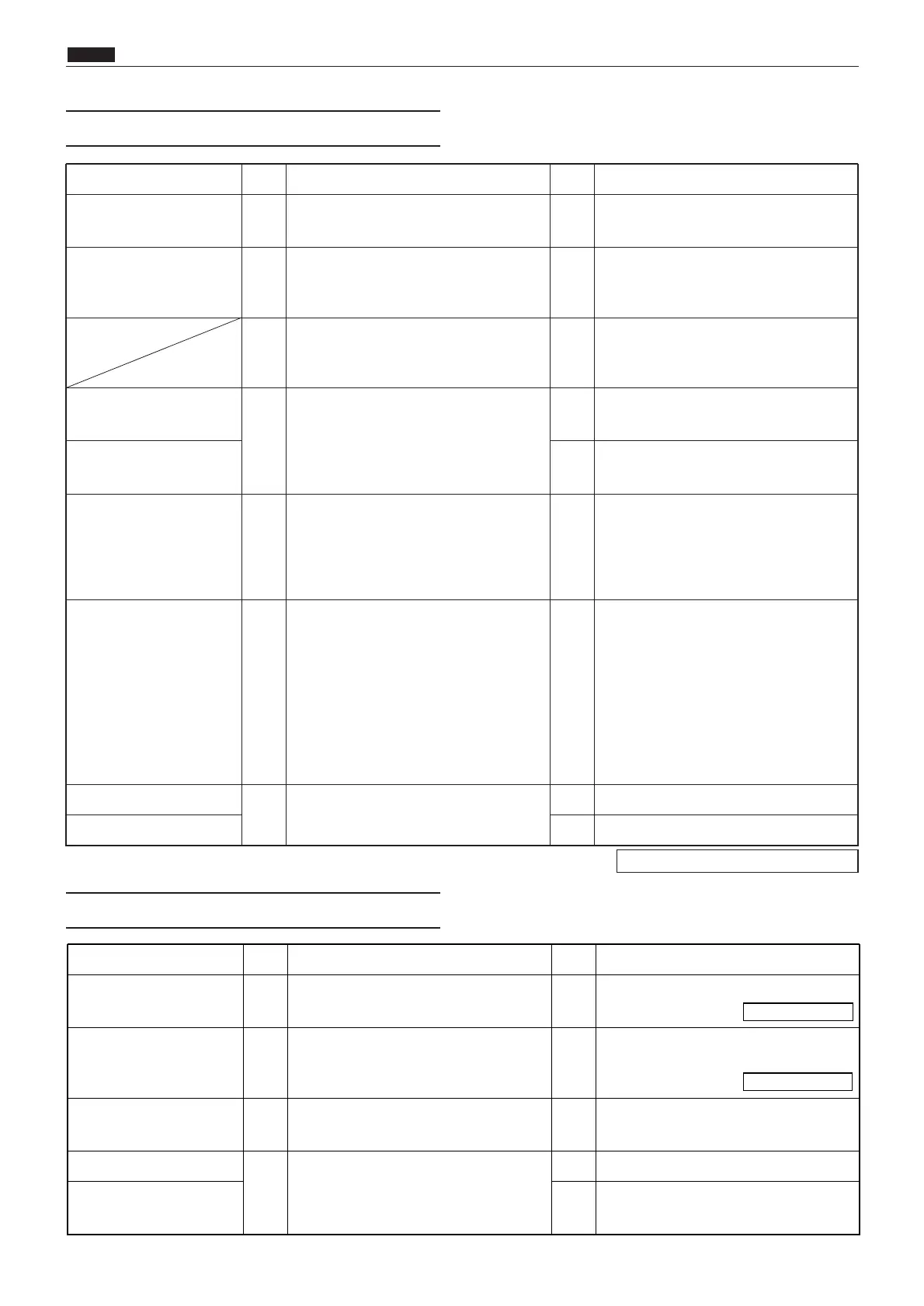
Cause/Detective section
Procedures
Result
CountermeasureItems to be checked
Master jams. 1 Does the master jam on the cutter unit? Yes Remove the jammed master.
Wire or timing belt is cut. 2
Are the wire and timing belt on the cut-
ter unit attached properly?
No Attach the wire and timing belt properly.
3
Check the cutter limit with the HELP
mode H-07*.
Is the cutter limit normal?
Yes Follow the procedure (5).
Cutter limit
4
Check the cutter limit switch with the
tester.
Is the switch turned on or off normally?
No
Replace the cutter limit (on the rear
side or front side).
Main PCB Unit Yes
Check the bundled wire and connector.
If OK, replace the main PCB Unit.
Regulated power supply 5
Remove the drive PCB Unit CN2.
Measure the voltage between the regu-
lated power supply CN2-1 (+) and CN2-
2 (GND) with the tester. Is the voltage
+24V?
No Regulated power supply.
Cutter motor 6
Check the voltage of the drive PCB Unit
CN2-17, CN2-18 with the tester when
the cutter motor relay connector is
inserted or removed.
Is the voltage +24V when the cutter
motor is moved to OPEN by the cutter
limit?
(+ or - reverse rotation depending on
the cutter motor operation direction)
Yes Replace the cutter motor.
Drive PCB Unit
7
Is the cause cleared by replacing the
drive PCB Unit?
Yes Finish
Cutter motor No Replace the cutter motor.
Cause/Detective section
Procedures
Result
CountermeasureItems to be checked
Lamp 1 Is lamp lit? No
See "The lamp Does not Light Up".
Optical system 2
Does the lamp advance to below the
shading plate?
No
See "The Optical System Does not
Move Forward/Backward".
Shading plate 3 Is the shading plate correctly installed? No Install the shading plate correctly.
AD PCB
4
Does replacing the AD PCB clear the
error?
Yes Finish
CCD PCB No
Adjust CCD PCB position, or replace
CCD PCB.
\See page 274
\See page 275