279
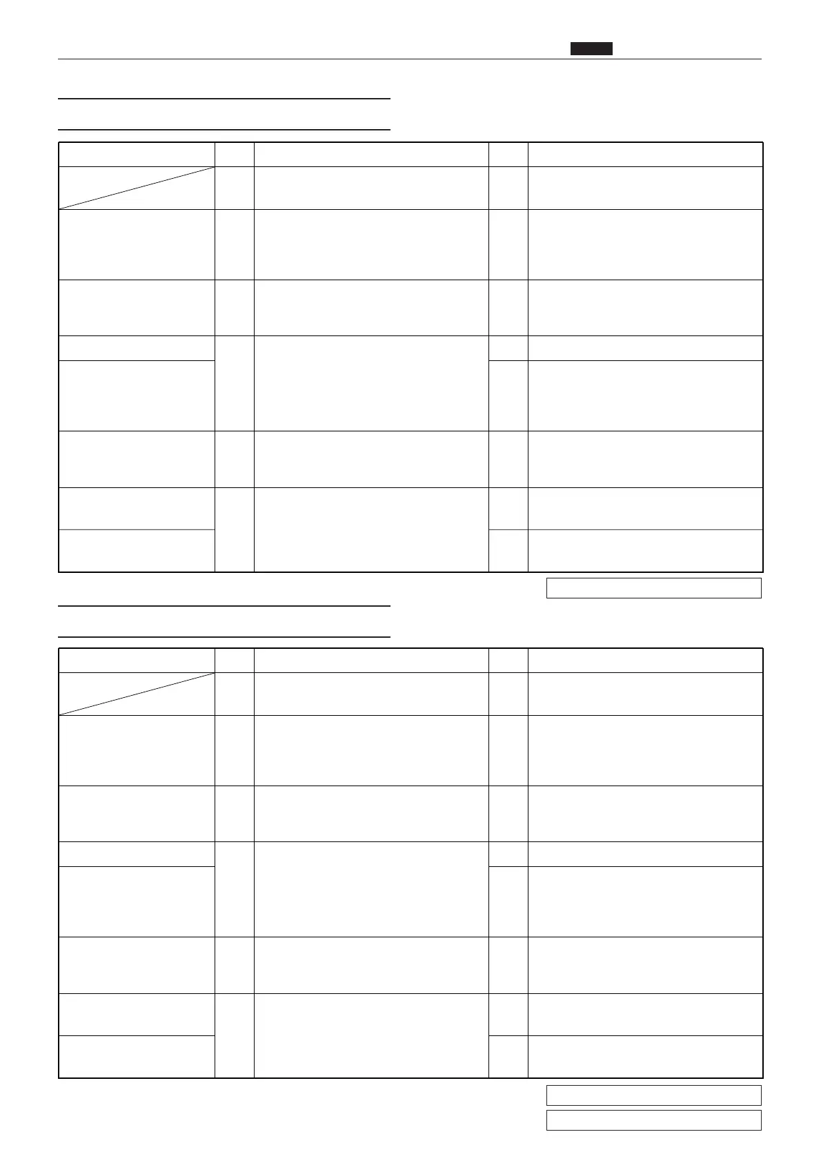
zTroubleshooting Guide
chap.6
Cause/Detective section
Procedures
Result
CountermeasureItems to be checked
1
Does ink roller motor turn when it is
checked using HELP01*?
Yes Follow the procedure (5).
Ink roller rise/descent
motor
2
Using a tester, measure the voltage
between CN2-5 (+) and CN2-6 (GND)
when the ink roller motor is activated
using HELP01. Is it +23V?
Yes
Check the bundled wire. If OK, replace
the ink roller rise/descent motor.
Regulated power supply 3
Measure voltage between CN2-1 (+)
and CN2-2 (GND) of the regulated
power supply. Is it +24V?
No Replace regulated power supply.
Drive PCB unit
4
Does replacing the drive PCB unit solve
the problem?
Yes Finish
Main PCB No
Check the connector and bundled wire
between the drive PCB unit CN5 and
the main PCB CN11. If OK, replace the
main PCB.
Ink roller rise/descent
switch position
5
Turn the ink roller rise/descent switches
on and off, and use HELP13 to check it.
Is on/off switching normal?
Yes
Adjust ink roller rise/descent switch
position.
Ink roller rise/descent
switches
6
Turn the ink roller rise/descent switches
on and off, and use a tester to measure
voltage. Is voltage normal?
No
Replace ink roller rise/descent
switches.
Main PCB Yes
Check the bundled wire. If OK, replace
the main PCB.
Cause/Detective section
Procedures
Result
CountermeasureItems to be checked
1
Does contact pressure motor turn when
it is checked using HELP01*?
Yes Follow the procedure (5).
Contact pressure motor 2
Using a tester, measure the voltage
between CN2-5 (+) and CN2-6 (GND)
when the contact pressure motor is
activated using HELP01*. Is it +23V?
Yes
Check the bundled wire. If OK, replace
the contact pressure motor.
Regulated power supply 3
Measure voltage between CN2-1 (+)
and CN2-2 (GND) of the regulated
power supply. Is it +24V?
No Replace the regulated power supply.
Drive PCB unit
4
Does replacing the drive PCB unit solve
the problem?
Yes Finish
Main PCB No
Check the connector and bundled wire
between the drive PCB unit CN5 and
the main PCB CN11. If OK, replace the
main PCB.
Contact pressure switch
position
5
Turn the contact pressure switches on
and off, and use HELP13** to check
them. Is on/off switching normal?
Yes Adjust contact pressure switch position.
Contact pressure switch-
es
6
Turn the contact pressure switches on
and off, and use a tester to measure
voltage. Is voltage normal?
No Replace contact pressure switches.
Main PCB Yes
Check the bundled wire. If OK, replace
the main PCB.
(8) E005 is Displayed
HELP mode H-01 \ see p.295
*
(9) E006 is Displayed
HELP mode H-01 \ see p.295
*
HELP mode H-13 \ see p.313
**