2. Replacement and adjustment of parts
26710
3/6
26710
Laser unit
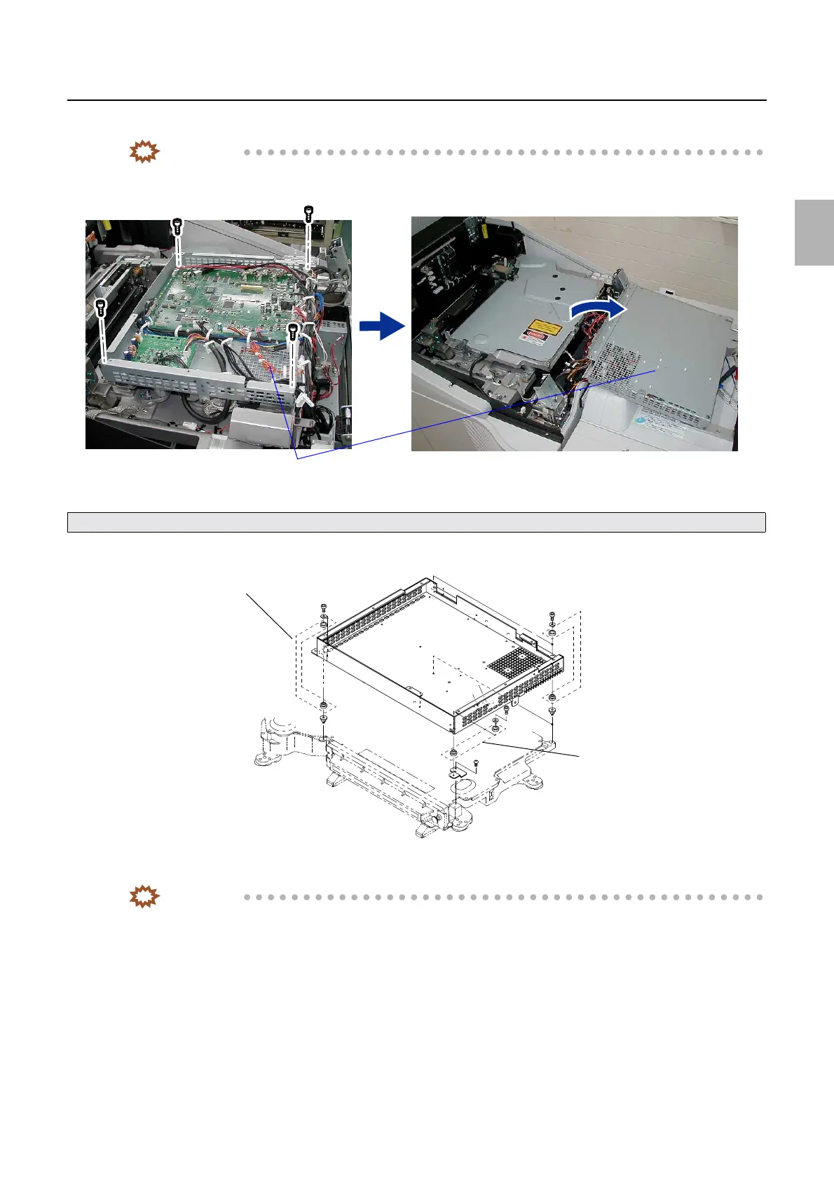
11. Remove the laser control box. (four screws)
IMPORTANT
• Remove the laser control box. Turn it over and place on the processor top cover.
• Do not lose the four vibration-proof rubbers of the laser control box.
12. Remove three vibration-proof mounts and a vibration-proof angle bracket. (two screws)
IMPORTANT
• This step is required only when you replace the laser unit with new one.
Take care for the wiring connected to the laser control PCB and perform the operation.
Laser control box
G085238
Vibration-proof rubber
Vibration-proof rubber
Vibration-proof rubber
G085239
Distributed by: minilablaser.com