2/10
2. Replacement and adjustment of parts
26820
26820
Zigzag adjustment
4. Enter the measured value into Paper Guide Width Measurement Value.
5. Perform 130.0 mm Width Operation Confirmation via Functions and confirm that the dimension between outsides of
the paper guides is 130.0 mm.
NOTE
• The acceptable value of the dimension between the paper guides is from 129.8 mm to 130.0 mm.
4. Confirming the paper center of paper supply unit A2
Confirm that magazine mount A2 and paper supply unit A2 are mutually adjusted.
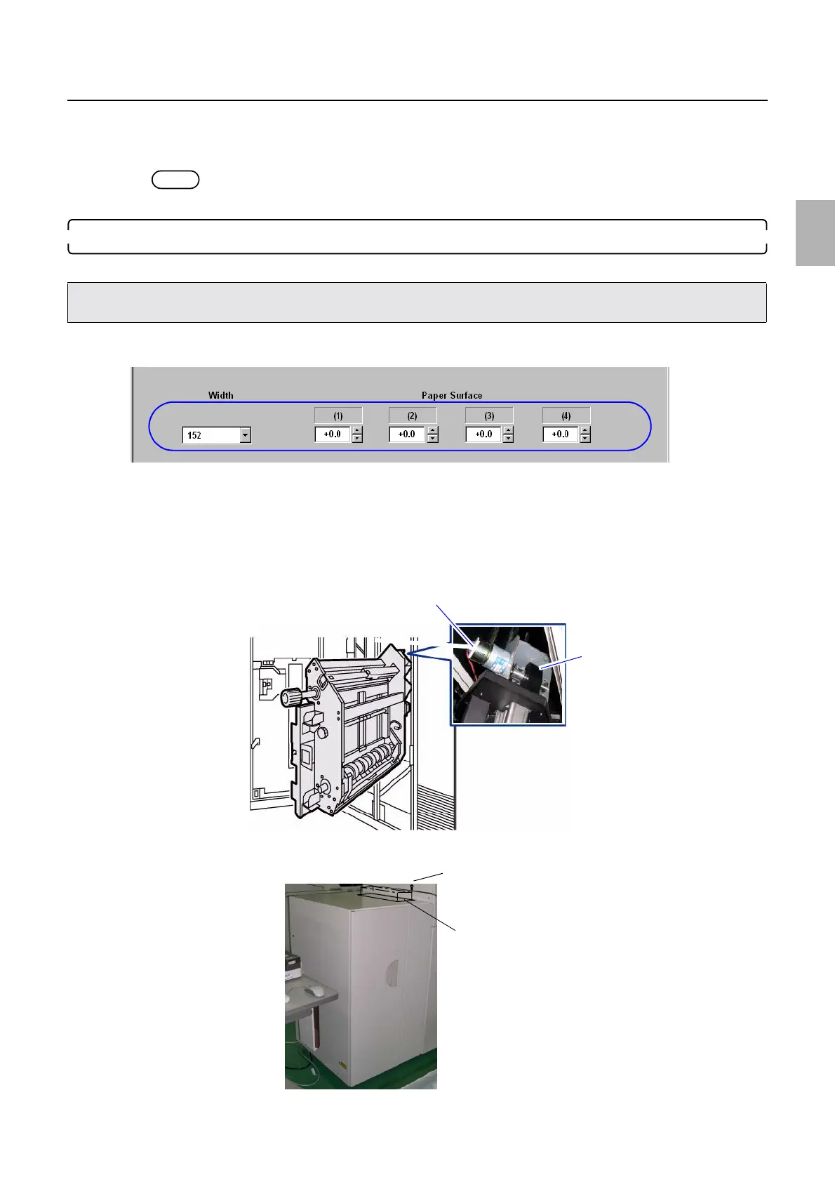
1. If the correction value is entered in Paper width (152.0 mm) of Paper Guide Width Adjustment (for each Paper
Width), enter 0.0 mm.
2. Set the paper width to 152.0 mm via Paper Guide Width Adjustment (for each Paper Width)→F:
Functions→Guide Width Test.
Bringing up the display
On the Maintenance Application display, click Maintenance. → Extension → Maintenance → Various Adjustment →
Printer Mechanical Adjustment → Paper Guide Width Adjustment (for each Paper Width)
3. Turn the cam section of the pressure release motor by hand and make the advance roller into the pressure condition.
4. Remove the top cover from the quad magazine unit. (four screws)
• Use paper whose width is 152 or 127 mm when confirming the paper center of paper supply unit A2.
• If those types of paper is not available, use the often-used paper of which width is 254 mm or less.
M5398-01
Pressure release motor
Cam
G089699
Screws
Cover
G086496
Distributed by: minilablaser.com