4. Troubleshooting
4302
3/3
4302
Diagnosis appendix: Diagnosis flowchart
2. Make a diagnosis via the displayed temperature on the R laser unit temperature sensor.
*1. The list below shows R laser thermosensor resistance values by temperature.
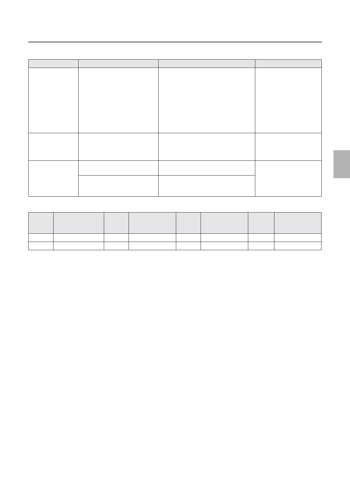
Checking point Checking content How to check Failure part
R laser temperature
control section
Peltier control voltage • If the voltage between Pin 3 of J1532
and laser control PCB (GND) is less
than 24 V
• If the voltage between Pin 2 of J1532
and laser control PCB (GND) is 0 V or
more and less than 0.8 V
• When heated: 0 V or more and
less than 0.8 V
• When it is off: 0 V
Laser unit (R laser
temperature control section)
R Laser
Thermosensor
*1
R laser thermosensor resistance
value
Remove J1504 and measure the resistance
value between Pin 1 (+) and 2(−). It is
normal if the resistance value is the same as
the value in the list below.
*1
Laser unit (R laser unit
thermosensor)
Laser control PCB R laser unit thermosensor standard
voltage
It is normal if the standard voltage between
Pin 1 (+) and 3 (−) of J1504 is 1 V.
Laser control PCB
R laser thermosensor measuring
voltage
It is normal if the voltage between Pin 2 (+)
and 3 (−) of J1504 is around 350 mV under
28°C temperature.
TEMPE
RATUR
E
Resistance TEMPE
RATUR
E
Resistance TEMPE
RATUR
E
Resistance TEMPER
ATURE
Resistance
5 11.4 kΩ to 12.7 kΩ 10 9.2 kΩ to 10.3 kΩ 15 7.4 kΩ to 8.5 kΩ 20 6.0 kΩ to 7.0 kΩ
25 5.0 kΩ to 5.8 kΩ 30 4.1 kΩ to 4.8 kΩ 35 3.4 kΩ to 4.0 kΩ
Distributed by: minilablaser.com