(due to retries), increasing message error counts, erratic communications, and in the worst case, complete
failure to communicate.
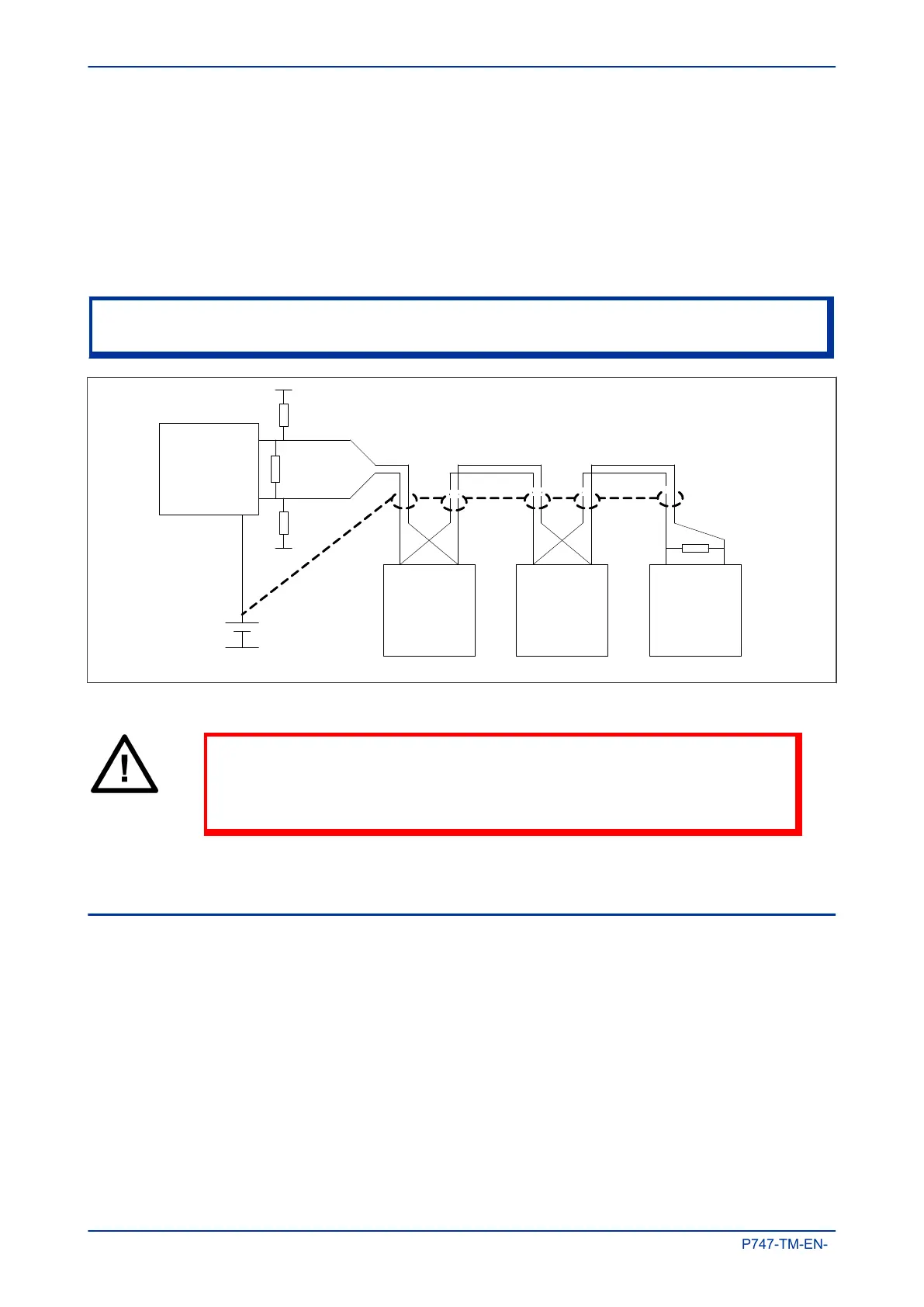
3.2.1 EIA(RS)485 BIASING REQUIREMENTS
Biasing requires that the signal lines be weakly pulled to a defined voltage level of about 1 V. There should
only be one bias point on the bus, which is best situated at the master connection point. The DC source used
for the bias must be clean to prevent noise being injected.
Note:
Some devices may be able to provide the bus bias, in which case external components would not be required.
V01000
Master
6 – 9 V DC
0
V
120 Ω
1
80 Ω bias
180 Ω bias
Slave Slave Slave
120 Ω
Figure 47: RS485 biasing circuit
Warning:
It is extremely important that the 120 Ω
termination resistors are fitted.
Otherwise the bias voltage may be excessive and may damage the devices
connected to the bus.
It is possible to use the product’s field voltage output (48 V DC) to bias the bus using values of 2.2 kΩ 0.5 W
bias resistors instead of the 180
Ω resistors shown in the above diagram. If using the field voltage, please
heed the following warnings.
3.3 K-BUS
K-Bus is a robust signalling method based on RS485 voltage levels. K-Bus incorporates message framing,
based on a 64
kbps synchronous HDLC protocol with FM0 modulation to increase speed and security.
The rear interface is used to provide a permanent connection for K-Bus, which allows multi-drop connection.
A K-Bus spur consists of up to 32 IEDs connected together in a multi-drop arrangement using twisted pair
wiring. The K-Bus twisted pair connection is non-polarised.
Two-core screened twisted pair cable should be used. The final cable specification is dependent on the
application, although a multi-strand 0.5 mm
2
per core is normally adequate. The total cable length must not
exceed 1000 m. It is important to avoid circulating currents, which can cause noise and interference,
especially when the cable runs between buildings. For this reason, the screen should be continuous and
connected to ground at one end only, normally at the master connection point.
Chapter 7 - SCADA Communications MiCOM P747
196 P747-TM-EN-1

 Loading...


