5.2.2 PROGRAMABLE LEDS
The device has a number of programmable LEDs, which can be associated with PSL-generated signals. All
of the programmable LEDs are tri-colour and can be set to RED, YELLOW or GREEN.
5.2.3 FUNCTION KEY LEDS
Adjacent to the function keys are programmable tri-colour LEDs. These should be associated with their
respective function keys.
5.2.4 TRIP LED LOGIC
When a trip occurs, the trip LED is illuminated. It is possible to reset this with a number of ways:
● Directly with a reset command (by pressing the Clear Key)
● With a reset logic input
● With self-resetting logic
You enable the automatic self-resetting with the Sys Fn Links cell in the SYSTEM DATA column. A '0'
disables self resetting and a '1' enables self resetting.
The reset occurs when the circuit is reclosed and the Any Pole Dead
signal has been reset for three
seconds providing the Any Start signal is inactive. The reset is prevented if the Any Start signal is active
after the breaker closes.
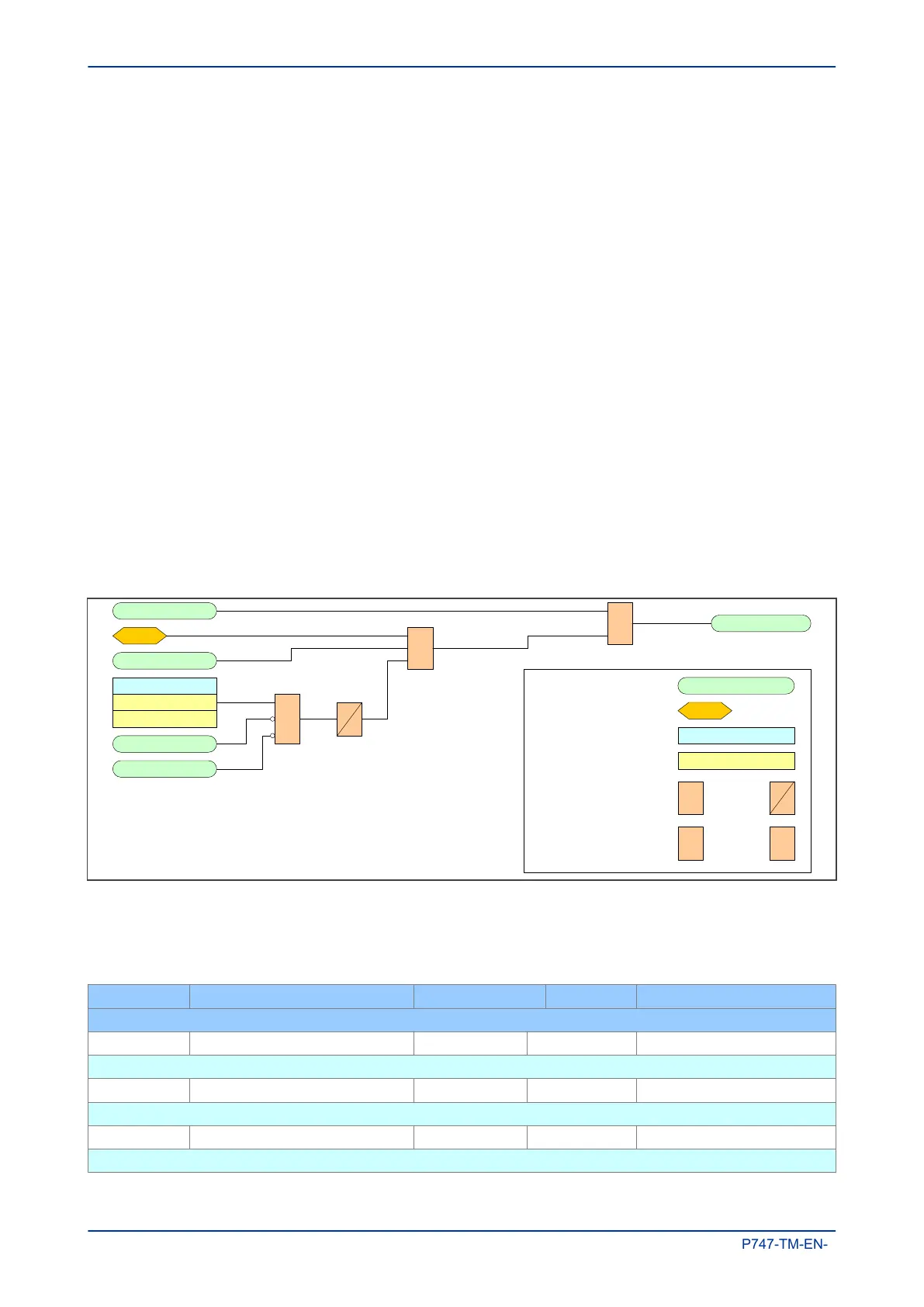
The Trip LED logic is as follows:
Any Pole Dead
Key:
External DDB Signal
&AND gate OR gate 1
Setting cell
Setting value
Timer
S
R
Q
S
R Latch
Trip LED Trigger
Any Start
Sys Fn Links
Disable Self Reset
Enable Self R eset
&
1
Any Trip
S
R
Q
Reset Relays/LED
V01211
Reset
H
MI Key
Figure 40: Trip LED logic
5.2.5 LED DDB SIGNALS
Ordinal Signal Name Source Type Response
Description
192 LED1 Red Software TRI LED NO RESPONSE
Tri-LED - 1 - Red (Programmable LED)
193 LED1 Grn Software TRI LED NO RESPONSE
Tri-LED - 1 - Green (Programmable LED)
194 LED2 Red Software TRI LED NO RESPONSE
Tri-LED - 2 - Red (Programmable LED)
Chapter 6 - Monitoring and Control MiCOM P747
170 P747-TM-EN-1

 Loading...


