6.6.2 TRANSFORMER BOARD
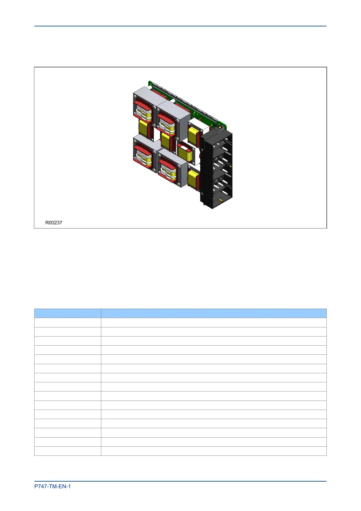
Figure 17: Instrument Transformer board
The transformer board hosts the current and voltage transformers, which are used to step down the currents
and voltages originating from the power systems' current and voltage transformers to levels, which can be
used by the unit’s electronic circuitry. In addition to this, the on-board CT and VT transformers provide
electrical isolation between the unit and the power system.
The transformer board is connected physically and electrically to the input board to form a complete input
module.
The terminal numbers are as follows:
Terminal Number Analogue Input Signal
Terminal 1 VT1, T1
Terminal 2 VT1, T2
Terminal 3 VT2, T3
Terminal 4 VT2, T4
Terminal 5
Terminal 6
Terminal 7
Terminal 8
Terminal 9
Terminal 10
Terminal 11 CT1
Terminal 12 CT1
Terminal 13 CT2
Terminal 14 CT2
Terminal 15 CT3
MiCOM P747 Chapter 3 - Hardware Design
P747-TM-EN-1 45

 Loading...


