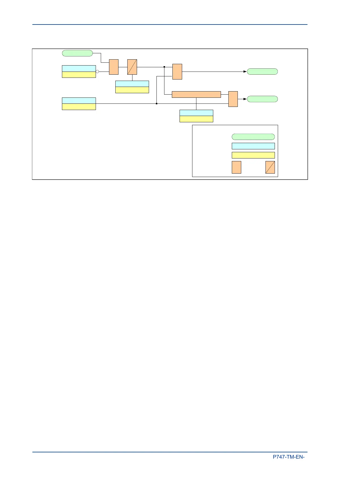
V00701
I< current set
0.5 to 4
&
I> current set
0.5 to 4
&
&
CB Fail 1 timer
0 to 10 secs
CB Fail 2 timer
0.04 to 10 secs
CB Fail 2 timer - CB Fail 1 timer
Back trip adjacent
z
one if CB failure
is bus coupler
CBF Retrip Tn
L
ocal retrip
CBF Bcktrip Zn
Int CBF Init Tn
I
nternal trip signal
Key:
&AND gate
Setting cell
Setting value
Timer
Internal DDB
Figure 36: CBF initiated by internal signal
If the faulty circuit breaker is on a feeder, a local retrip can be issued if CBF Retrip Tn is mapped to
appropriate outputs in the PSL. This may not be necessary if another protection on the feeder provides the
CB Fail function.
If the fault is on a busbar coupler circuit breaker, trip all adjacent circuit breakers in the zone by mapping
CBF Bktrip Zn
to appropriate outputs in the PSL.
The following diagram shows CBF logic for externally indicated faults. The digital input and output signals
(DDBs) that need mapping in the PSL are:
● Ext CBF INIT Tn (n=1-18)
● CBF Retrip Tn (n=1-18)
● CBF Bktrip Zn (n=1-4)
● CBF Bktrip Tn (n=1-18)
● Ext CBF Zn (n=1-4)
Chapter 5 - Protection Functions MiCOM P747
112 P747-TM-EN-1

 Loading...


