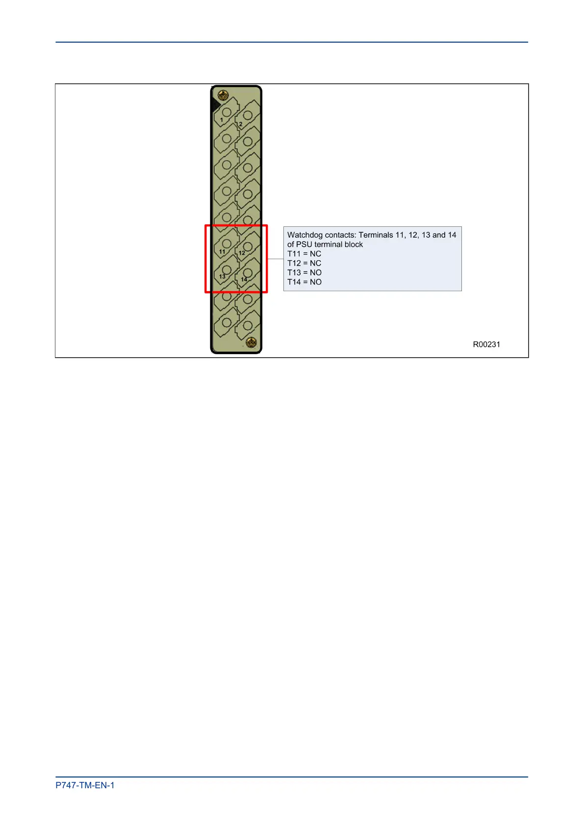
Figure 13: Watchdog contact terminals
6.5.2 REAR SERIAL PORT
For space reasons, the rear serial port (RP1) is also housed on the power supply board. This is a three-
terminal serial communications port, intended for use with a permanently wired connection to a remote
control centre. The physical connectivity is achieved using three screw terminals; two for the signal
connection, and the third for the earth shield of the cable. These are located on pins 16, 17 and 18 of the
power supply terminal block, which is on the far right looking from the rear. The interface can be selected
between RS485 and K-bus. When the K-Bus option is selected, the two signal connections are not polarity
conscious.
The polarity independent K-bus can only be used for the Courier data protocol. The polarity conscious
MODBUS, IEC 60870-5-103 and DNP3.0 protocols need RS485.
The following diagram shows the rear serial port. The pin assignments are as follows:
● Pin 16: Ground shield
● Pin 17: Negative signal
● Pin 18: Positive signal
MiCOM P747 Chapter 3 - Hardware Design
P747-TM-EN-1 41

 Loading...


