6 BOARDS AND MODULES
Each product comprises a selection of PCBs (Printed Circuit Boards) and sub-assemblies, depending on the
chosen configuration.
6.1 PCBS
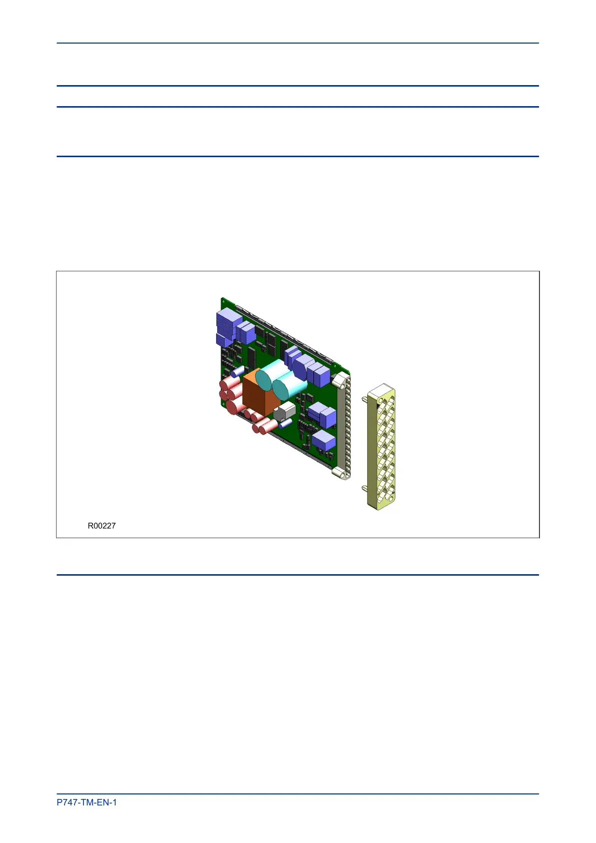
A PCB typically consists of the components, a front connector for connecting into the main system parallel
bus via a ribbon cable, and an interface to the rear. This rear interface may be:
● Directly presented to the outside world (as is the case for communication boards such as Ethernet
Boards)
● Presented to a connector, which in turn connects into a terminal block bolted onto the rear of the case
(as is the case for most of the other board types)
Figure 7: Rear connection to terminal block
6.2 SUBASSEMBLIES
A sub-assembly consists of two or more boards bolted together with spacers and connected with electrical
connectors. It may also have other special requirements such as being encased in a metal housing for
shielding against electromagnetic radiation.
Boards are designated by a part number beginning with ZN, whereas pre-assembled sub-assemblies are
designated with a part number beginning with GN. Sub-assemblies, which are put together at the production
stage, do not have a separate part number.
MiCOM P747 Chapter 3 - Hardware Design
P747-TM-EN-1 35

 Loading...


