2 HARDWARE ARCHITECTURE
The main components comprising devices based on the Px4x platform are as follows:
● The housing, consisting of a front panel and connections at the rear
● The Main processor module consisting of the main CPU (Central Processing Unit), memory and an
interface to the front panel HMI (Human Machine Interface)
● A selection of plug-in boards and modules with presentation at the rear for the power supply,
communication functions, digital I/O, analogue inputs, and time synchronisation connectivity
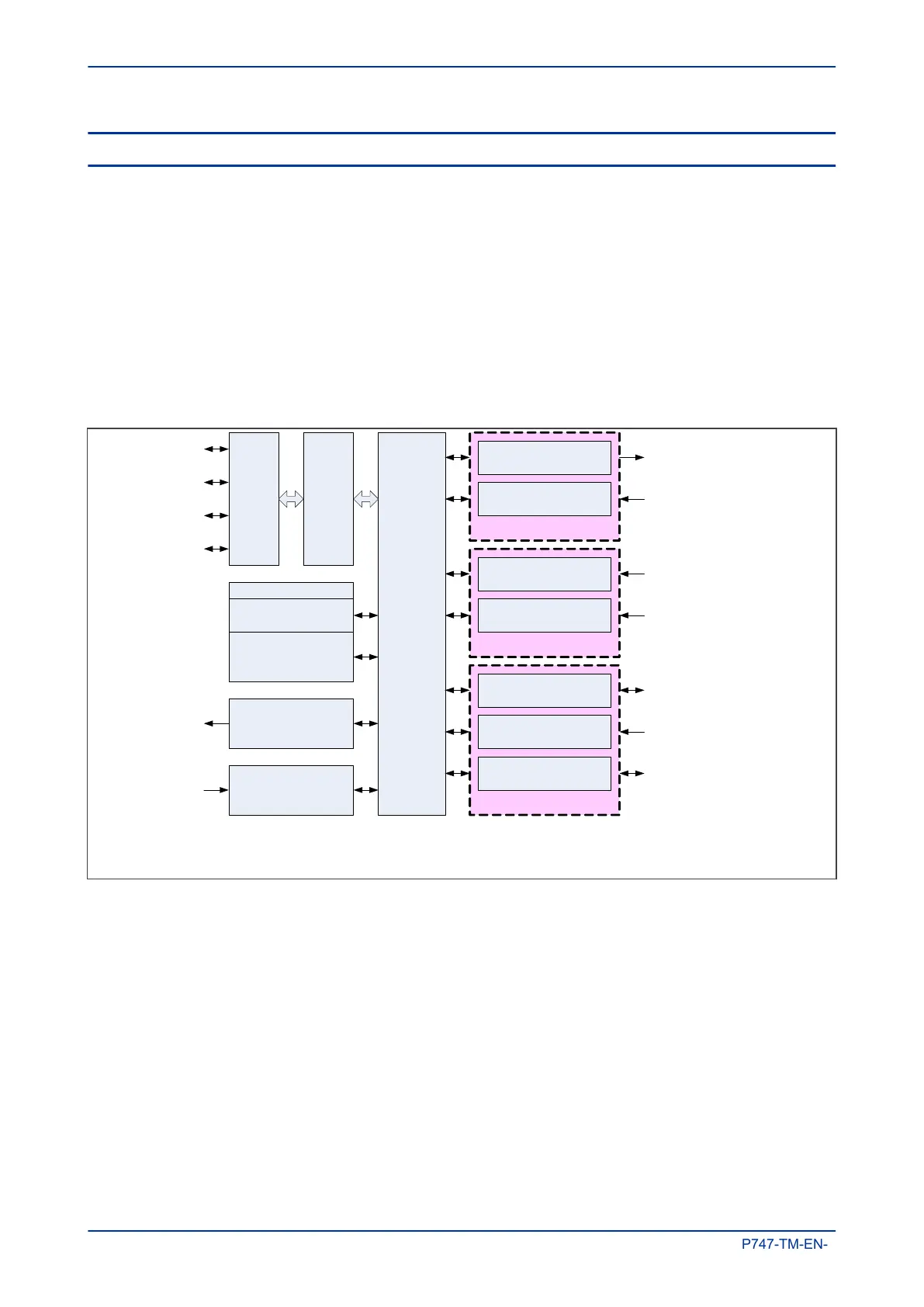
All boards and modules are connected by a parallel data and address bus, which allows the processor
module to send and receive information to and from the other modules as required. There is also a separate
serial data bus for conveying sampled data from the input module to the CPU. These parallel and serial
databuses are shown as a single interconnection module in the following figure, which shows typical
modules and the flow of data between them.
Communications
Analogue Inputs
I/O
I
n
t
e
r
c
o
n
n
e
c
t
i
o
n
Output relay boards
Opto-input boards
CTs
VTs
RS485 modules
Ethernet modules
Keypad
L
CD
LEDs
Front port
Watchdog module
PSU module
Watchdog
c
ontacts
+ LED
Auxiliary
Supply
IRIG-B module
P
r
o
c
e
s
s
o
r
m
o
d
u
l
e
F
r
o
n
t
p
a
n
e
l
H
M
I
Output relay contacts
Digital inputs
P
ower system currents
Power system voltages
RS485 communication
Time synchronisation
Ethernet communication
V00233
Note: Not all modules are applicable to all products
Memory
Flash memory for settings
Battery-backed SRAM
for records
Figure 2: Hardware architecture
Chapter 3 - Hardware Design MiCOM P747
26 P747-TM-EN-1

 Loading...


