Terminal Number Isolated digital input
Terminal 14 Isolated digital input 7 +ve
Terminal 15 Isolated digital input 8 –ve
Terminal 16 Isolated digital input 8 +ve
Terminal 17 Common
Terminal 18 Common
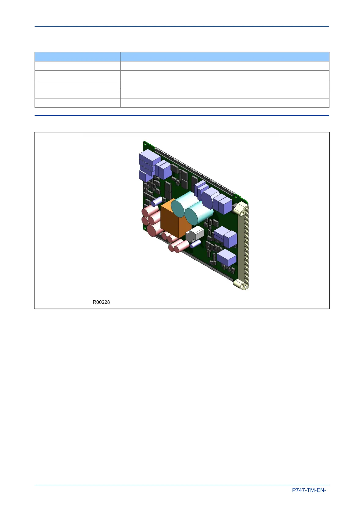
6.5 POWER SUPPLY BOARD
Figure 10: Power supply board
The power supply board provides power to the unit. One of three different configurations of the power supply
board can be fitted to the unit. This is specified at the time of order and depends on the nature of the supply
voltage that will be connected to it.
There are three board types, which support the following voltage ranges:
● 24/54 V DC
● 48/125 V DC
● 110/250 V DC
The power supply board connector plugs into a medium duty terminal block sliding in from the front of the
unit to the rear. This terminal block is always positioned on the right hand side of the unit looking from the
rear.
The power supply board is usually assembled together with the relay output board to form a complete sub-
assembly, as shown in the following diagram.
Chapter 3 - Hardware Design MiCOM P747
38 P747-TM-EN-1

 Loading...


