The input module consists of the main input board coupled together with two transformer boards. The
transformer boards contain the voltage and current transformers, which isolate and scale the analogue input
signals delivered by the system transformers. The input board contains the A/D conversion and digital
processing circuitry, as well as eight digital isolated inputs (opto-inputs).
The boards are connected together physically (bolted together with spacers) and electrically (via electrical
connectors). The module is encased in a metal housing for shielding against electromagnet radiation.
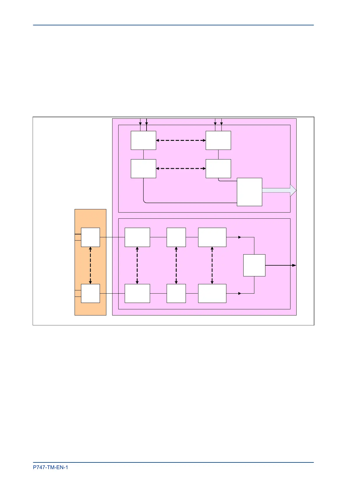
6.6.1 SIGMA-DELTA INPUT MODULE CIRCUIT DESCRIPTION
V00261
Transformer
b
oard
Serial
i
nterface
Serial Link
Optical
I
solator
Noise
f
ilter
Optical
I
solator
Noise
f
ilter
Buffer
8 digital inputs
Parallel Bus
VT
o
r
CT
Sigma-
D
elta
modulator
VT
o
r
CT
Digital
f
ilter
Digital
f
ilter
Sigma-
D
elta
modulator
Resampling
Resampling
Figure 16: Input module schematic
A/D Conversion
The differential analogue inputs from the unit’s CT and VT transformers are presented to the main input
board as shown. Each differential input is first converted to a single input quantity referenced to the input
board’s ground potential.
The sigma-delta modulators convert analogue to digital using high frequency sampling. A digital filter
removes several unwanted properties, then the signal is resampled to produce the required resolution digital
output. These samples are passed through a serial interface module which outputs data on the serial sample
data bus.
The calibration coefficients are stored in non-volatile memory. These are used by the processor board to
correct for any amplitude or phase errors introduced by the transformers and analogue circuitry.
MiCOM P747 Chapter 3 - Hardware Design
P747-TM-EN-1 43

 Loading...


