However, this is difficult to achieve in practice because the CTs can never have identical characteristics. A
fault from another zone that causes a high current to pass through is classed as a through fault. In this case
the CTs need to be able to cope without saturating. However, for very large through faults they do saturate
and each saturates differently. The term used to specify the system’s ability to cope with these imperfections
is called Through Fault Stability.
2.3 THROUGH FAULT STABILITY
With any form of differential protection, it is important that the CTs have the same characteristics. This is to
avoid unnecessarily creating a differential current. However, in reality CTs can never be identical, therefore a
certain amount of differential current is inevitable. As the through-fault current in the primary increases, the
discrepancies introduced by the imperfectly matched CTs is magnified, causing the differential current to
build up. Eventually, the value of the differential current reaches the pickup current threshold, causing the
IED to trip. In such cases, the differential scheme is said to have lost stability. To specify a differential
scheme’s ability to restrain from tripping on external faults, we define a parameter called ‘through-fault
stability limit’, which is the maximum through-fault current a system can handle without losing stability.
2.4 BIAS CURRENT COMPENSATION
Any difference between CTs in a current differential scheme causes a spill current when the system is
healthy. To prevent false operation under these conditions, compensation is needed to remain sensitive to
real faults yet ignore through faults. This is done by applying a proportion of the scalar sum of all the currents
entering and exiting the zone. This scalar sum is called bias current.
The bias characteristic changes the operating point of the IED depending on the fault current. At low
through-fault currents, the CT performance is more reliable so a low bias current is needed. Less differential
current is then needed to trip the breakers, allowing greater sensitivity to internal faults. At high through-fault
currents, the CTs may be close to saturation so a high bias current is needed. More differential current is
then needed to trip the breakers, allowing greater security from external faults and less risk of maloperation.
The IED compares the differential current with the bias current characteristic. The IED trips if the differential
current exceeds the bias current at any point on the characteristic. Normally a lower threshold is set on the
characteristic. This prevents tripping below normal full-load current.
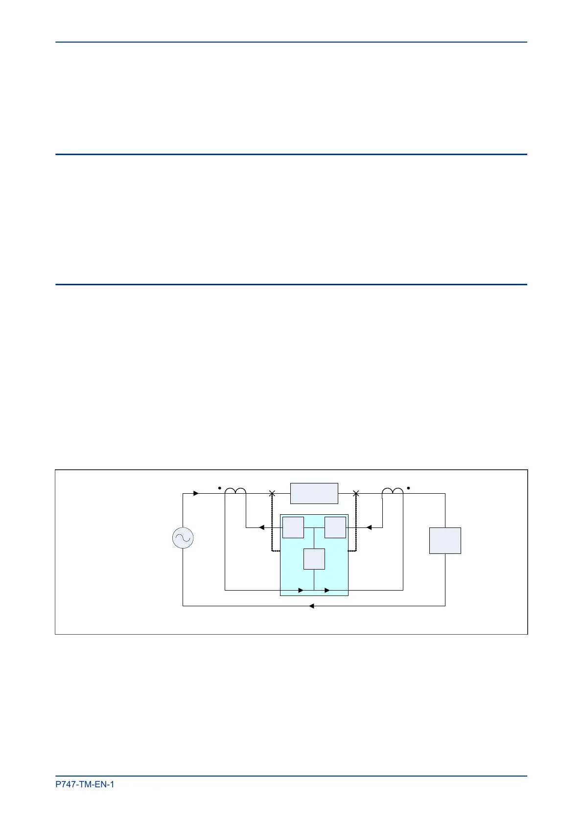
V00668
CB A
CT A
CB B
Source
Load
Idiff
C
T B
Trip Trip
I
L
I
L
I
L
I
L
/
n I
L
/n
Ibias Ibias
Protected
e
quipment
The following diagram shows a typical bias characteristic, where:
Idiff
is the differential current, whichis the vector sum of all the currents entering and leaving the zone.
Ibias is proportional to the scalar sum of all the currents entering and leaving the zone.
The characteristic can be defined by setting certain parameters, where:
K1 is the slope
IS1 is the minimum operating current
IS2 is the level of bias current at which the steeper slope begins
MiCOM P747 Chapter 5 - Protection Functions
P747-TM-EN-1 101

 Loading...


