4 CABLES AND CONNECTORS
This section describes the type of wiring and connections that should be used when installing the device. For
pin-out details please refer to the Hardware Design chapter or the wiring diagrams.
Caution:
Before carrying out any work on the equipment you should be familiar with the
Safety Section and the ratings on the equipment’s rating label.
4.1 TERMINAL BLOCKS
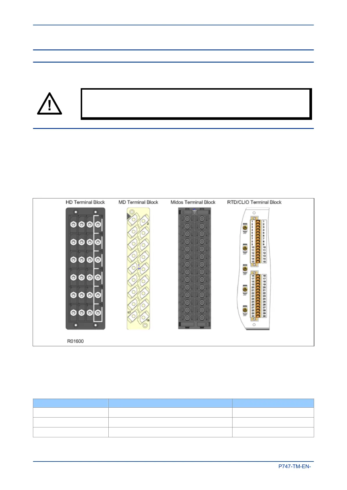
The device may use one or more of the terminal block types shown in the following diagram. The terminal
blocks are fastened to the rear panel with screws.
● Heavy duty (HD) terminal blocks for CT and VT circuits
● Medium duty (MD) terminal blocks for the power supply, relay outputs and rear communications port
● MiDOS terminal blocks for CT and VT circuits
● RTD/CLIO terminal block for connection to analogue transducers
Figure 92: Terminal block types
MiCOM products are supplied with sufficient M4 screws for making connections to the rear mounted terminal
blocks using ring terminals, with a recommended maximum of two ring terminals per terminal.
If required, M4 90° crimp ring terminals can be supplied in three different sizes depending on wire size. Each
type is available in bags of 100.
Part number Wire size Insulation color
ZB9124 901
0.25 - 1.65 mm
2
(22 – 16 AWG)
Red
ZB9124 900
1.04 - 2.63 mm
2
(16 – 14 AWG)
Blue
ZB9124 904
2.53 - 6.64 mm
2
(12 – 10 AWG)
Un-insulated
Chapter 13 - Installation MiCOM P747
336 P747-TM-EN-1

 Loading...


