2.1.3 REMOVE CONNECTION
To remove a connection:
1.
Select a connection.
2. Pess the Delete key or click the Remove icon.
2.2 SCHEME ELEMENTS
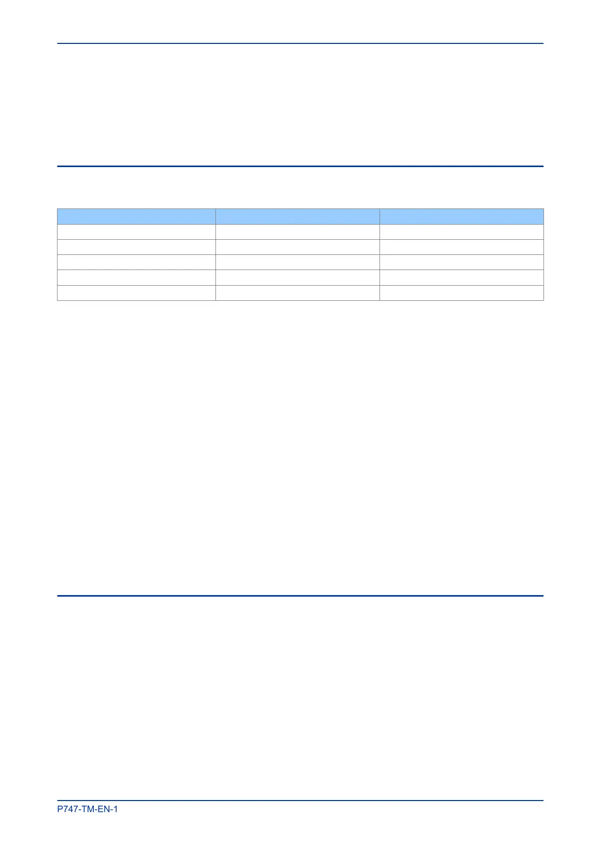
The following table shows the number of elements allowed in a scheme.
Element Minimum number Maximum number
Busbar 1 4
Isolator 2 74
Circuit Breaker 2 18
Current Transformer 2 18
Voltage Transformer 0 4
2.2.1 ADD ELEMENTS TO A SCHEME
To add elements to a scheme, drag and drop them from the toolbox.
2.2.2 REMOVE AN ELEMENT
To remove an element from a scheme:
1.
Select an element.
2. Pess the Delete key or click the Remove icon.
2.2.3 GROUP ELEMENTS IN A SCHEME
To group elements in a scheme:
1.
Drag and drop the elements into the scheme.
2. Add any connections between them.
3. Select the elements you want to group.
4. Click the Group icon.
2.2.4 ROTATE ELEMENTS IN A GROUP
To rotate an element or group, select the item and click the Rotate Left or Rotate Right icon.
2.3 WORKING WITH TEXT ON THE SCHEME
You can add labels or free text onto the scheme:
● Circuit Breakers can be labelled CB1 to CB18.
● Current Transformers can be labelled CT1 to CT18.
● Voltage Transformers can be labelled VT1 to VT4.
● Feeder Isolators can be labelled QxZy where x=1 to 18 and y=1 to 4.
● Busbar Isolators can be labelled QBus1 to Qbus2.
MiCOM P747 Chapter 11 - Busbar Commissioning Tool
P747-TM-EN-1 307

 Loading...


