7.1.1 PSL FOR TCS SCHEME 1
Opto-input
V
01217
Key: External DDB Signal
T
ime Delay
&Inverter
&
NC Output Relay
LED
User Alarm
pickup
0
5
0
0
4
00
dropoff
straight
0
0
Latching
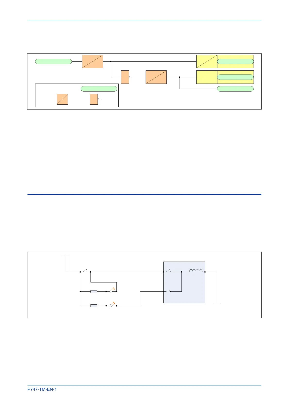
Figure 42: PSL for TCS Scheme 1
The opto-input can be used to drive a Normally Closed Output Relay, which in turn can be used to drive
alarm equipment. The signal can also be inverted to drive a latching programmable LED and a user alarm
DDB signal.
The DDO timer operates as soon as the opto-input is energised, but will take 400 ms to drop off/reset in the
event of a trip circuit failure. The 400 ms delay prevents a false alarm due to voltage dips caused by faults in
other circuits or during normal tripping operation when the opto-input is shorted by a self-reset trip contact.
When the timer is operated the NC (normally closed) output relay opens and the LED and user alarms are
reset.
The 50 ms delay on pick-up timer prevents false LED and user alarm indications during the power up time,
following a voltage supply interruption.
7.2 TRIP CIRCUIT SUPERVISION SCHEME 2
Much like TCS scheme 1, this scheme provides supervision of the trip coil with the breaker open or closed
but does not provide pre-closing supervision of the trip path. However, using two opto-inputs allows the IED
to correctly monitor the circuit breaker status since they are connected in series with the CB auxiliary
contacts. This is achieved by assigning Opto-input 1 to the 52a contact and Opto-input 2 to the 52b contact.
Provided the Circuit Breaker Status setting in the CB CONTROL column is set to 52a and 52b, the IED
will correctly monitor the status of the breaker. This scheme is also fully compatible with latched contacts as
the supervision current will be maintained through the 52b contact when the trip contact is closed.
V01215
52A
52B
R
1
Trip Output Relay
+
ve
-ve
Opto-input 1
R2
Opto-input 2
Circuit Breaker
T
rip path
Trip coil
Figure 43: TCS Scheme 2
When the breaker is closed, supervision current passes through opto input 1 and the trip coil. When the
breaker is open current flows through opto input 2 and the trip coil. As with scheme 1, no supervision of the
trip path is provided whilst the breaker is open. Any fault in the trip path will only be detected on CB closing,
after a 400
ms delay.
MiCOM P747 Chapter 6 - Monitoring and Control
P747-TM-EN-1 189

 Loading...


