2 BUSBAR PROTECTION
A protection scheme for a power system should cover the whole system against all probable types of fault.
Unrestricted forms of line protection, such as overcurrent and distance systems, meet this requirement, but
clear faults in the busbar zone only after a time delay. If unit protection is applied to feeders and plant, the
busbars are not inherently protected.
Busbars are often left without specific protection since the risk of a fault occurring on modern gear is
considered to be small. However, the damage resulting from one uncleared fault may be extensive.
Busbar protection is needed when the system protection does not cover the busbars or when high-speed
fault clearance is needed to maintain power system stability. Unit busbar protection provides this. Also if the
busbars are sectionalised, only one section needs to be isolated to clear a fault.
Busbar faults generate large fault currents and must be cleared quickly, otherwise the whole substation is at
risk due to both dynamic forces and thermal effects. Therefore busbar protection must provide high-speed
operation. A false trip on a distribution bus can affect many customers as feeders and transmission lines are
disconnected. Also a false trip on a transmission busbar can seriously affect power system stability.
Therefore busbar protection must provide maximum security.
2.1 UNIT PROTECTION
In large power networks, tripping times of protection equipment can vary depending on the distance from the
fault. To reduce this, power networks can be divided into protection zones. Values can be compared at zone
boundaries to narrow the fault to a specific zone. Each zone can detect and isolate its own faults. The zone
can cover several items of equipment such as a busbar or just one item such as a transmission line,
transformer, motor or generator. This is known as Unit Protection.
2.2 CURRENT DIFFERENTIAL PROTECTION PRINCIPLES
One form of Unit Protection is called Current Differential Protection. This was first defined by Merz and Price
using Kirchoff's current law. It compares currents entering and leaving a unit. If there is no fault, the current
that enters is the same as the current that leaves, so the difference is zero. If there is a fault, the difference is
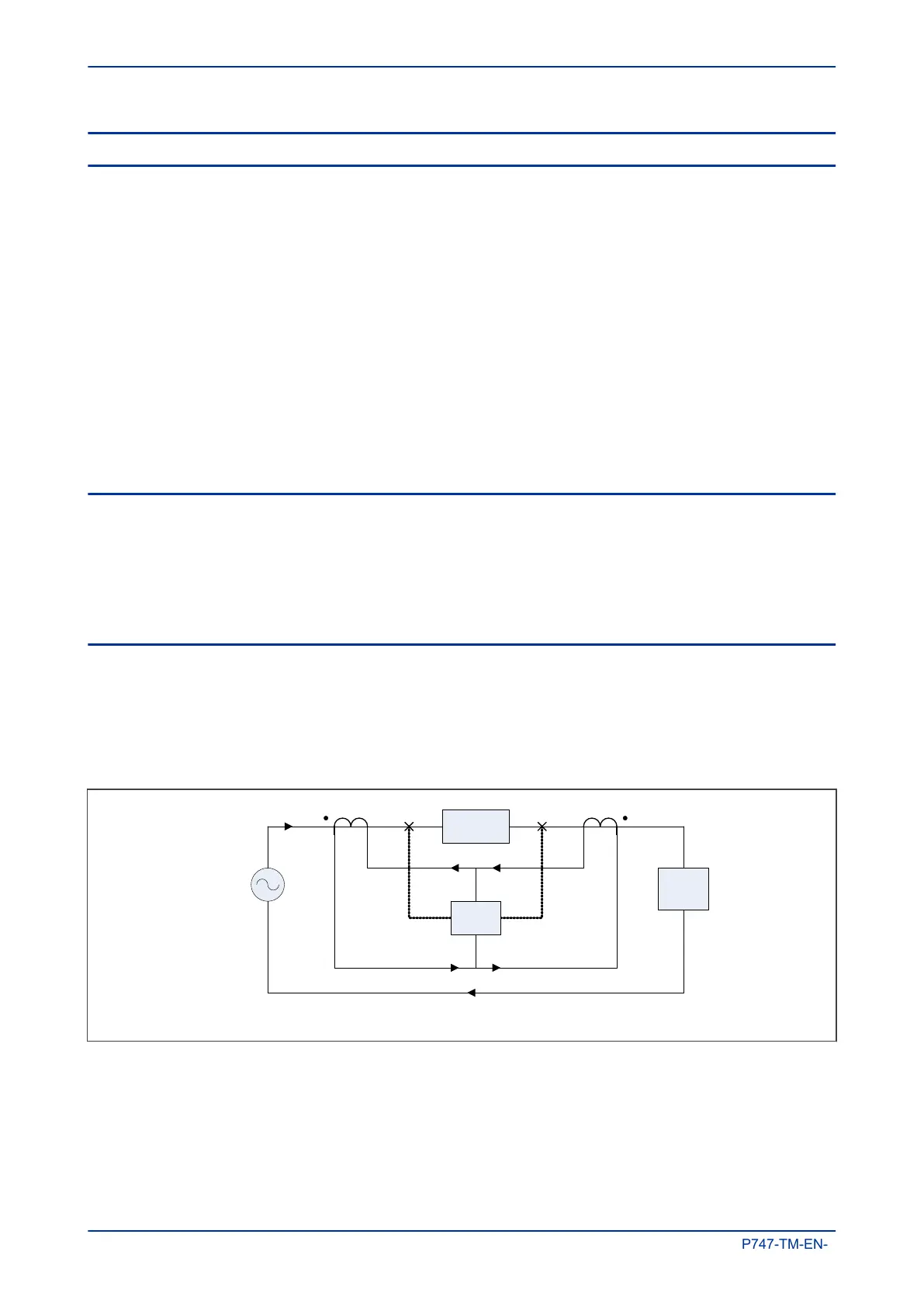
equal to the fault current. The following diagram shows two current transformers (CTs), one at each end of a
protected zone. If there is a fault between the two CTs, a current flows through the IED.
V00712
CB A
CT A
CB B
Source
Load
IED
C
T B
Trip Trip
I
L
I
L
I
L
I
L
/
n I
L
/n
Idiff
Protected
e
quipment
Figure 27: Current Differential Protection
The differential scheme creates a well-defined protection zone between the two CTs. Any fault in the
differential protection zone is an internal fault, while any fault outside is an external fault. The protection
needs to operate only for faults in the protection zone and to be sensitive to low fault currents. Theoretically
a differential scheme should respond to the smallest internal faults but restrain on the largest external faults.
Chapter 5 - Protection Functions MiCOM P747
100 P747-TM-EN-1

 Loading...


