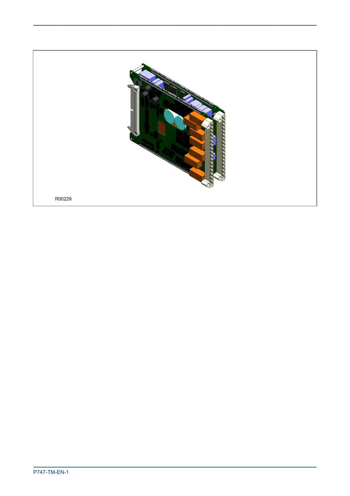
Figure 11: Power Supply Assembly
The power supply outputs are used to provide isolated power supply rails to the various modules within the
unit. Three voltage levels are used by the unit’s modules:
● 5.1 V for all of the digital circuits
● +/- 16 V for the analogue electronics such as on the input board
● 22 V for driving the output relay coils.
All power supply voltages, including the 0 V earth line, are distributed around the unit by the 64-way ribbon
cable.
The power supply board incorporates inrush current limiting. This limits the peak inrush current to
approximately 10 A.
Power is applied to pins 1 and 2 of the terminal block, where pin 1 is negative and pin 2 is positive. The pin
numbers are clearly marked on the terminal block as shown in the following diagram.
MiCOM P747 Chapter 3 - Hardware Design
P747-TM-EN-1 39

 Loading...


