Terminal Number Analogue Input Signal
Terminal 16 CT3
Terminal 17 CT4
Terminal 18 CT4
Terminal 19 CT5
Terminal 20 CT5
Terminal 21 CT6
Terminal 22 CT6
Terminal 23 CT7
Terminal 24 CT7
Terminal 25 CT8
Terminal 26 CT8
Terminal 27 CT9
Terminal 28 CT9
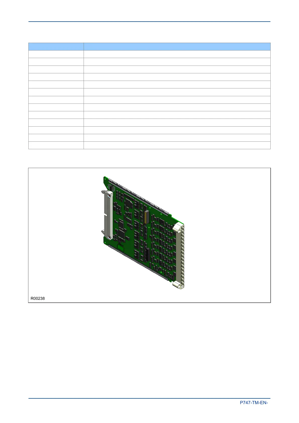
6.6.3 MAIN INPUT BOARD
Figure 18: Main input board
The input board is used to convert the analogue signals delivered by the current and voltage transformers
into digital quantities used by the IED. This input board also has on-board opto-input circuitry, providing eight
optically-isolated digital inputs and associated noise filtering and buffering. These opto-inputs are presented
to the user by means of a MD terminal block, which sits adjacent to the analogue inputs terminal block.
The input board is connected physically and electrically to the transformer board to form a complete input
module.
The main input board can come in several different variants depending on the exact model. The terminal
numbers of the opto-inputs are as follows:
Chapter 3 - Hardware Design MiCOM P747
46 P747-TM-EN-1

 Loading...


