2 INTRODUCTION TO THE SCHEME LOGIC
The Scheme Logic is a functional module within the IED, through which all mapping of inputs to outputs is
handled. The scheme logic can be split into two parts; the Fixed Scheme Logic (FSL) and the Programmable
Scheme Logic (PSL).
The FSL Scheme Logic is logic that has been designed and implemented at the factory. It is logic that is
necessary for the fundamental workings of the IED. It is fixed and cannot be changed.
The PSL is logic that is user-programmable. The PSL consists of logic gates and timers, which combine and
condition the DDB signals. The logic gates can be programmed to perform a range of different logic functions
and can accept any number of inputs. The timers are used either to create a programmable delay or to
condition the logic outputs. There are also counters available. The PSL logic is event driven. Only the part of
the PSL logic that is affected by the particular input change that has occurred is processed. This reduces the
amount of processing time used by the PSL, when compared to some competition devices. The device is
shipped with a selection of default schemes, which should cover basic applications, but you can modify
these default schemes to create custom schemes, if desired. You can also create new schemes from
scratch, should you wish to do so.
The Scheme Logic module is built around a concept called the digital data bus (DDB). The DDB is a parallel
data bus containing all of the digital signals (inputs, outputs, and internal signals), which are available for use
in the FSL and PSL
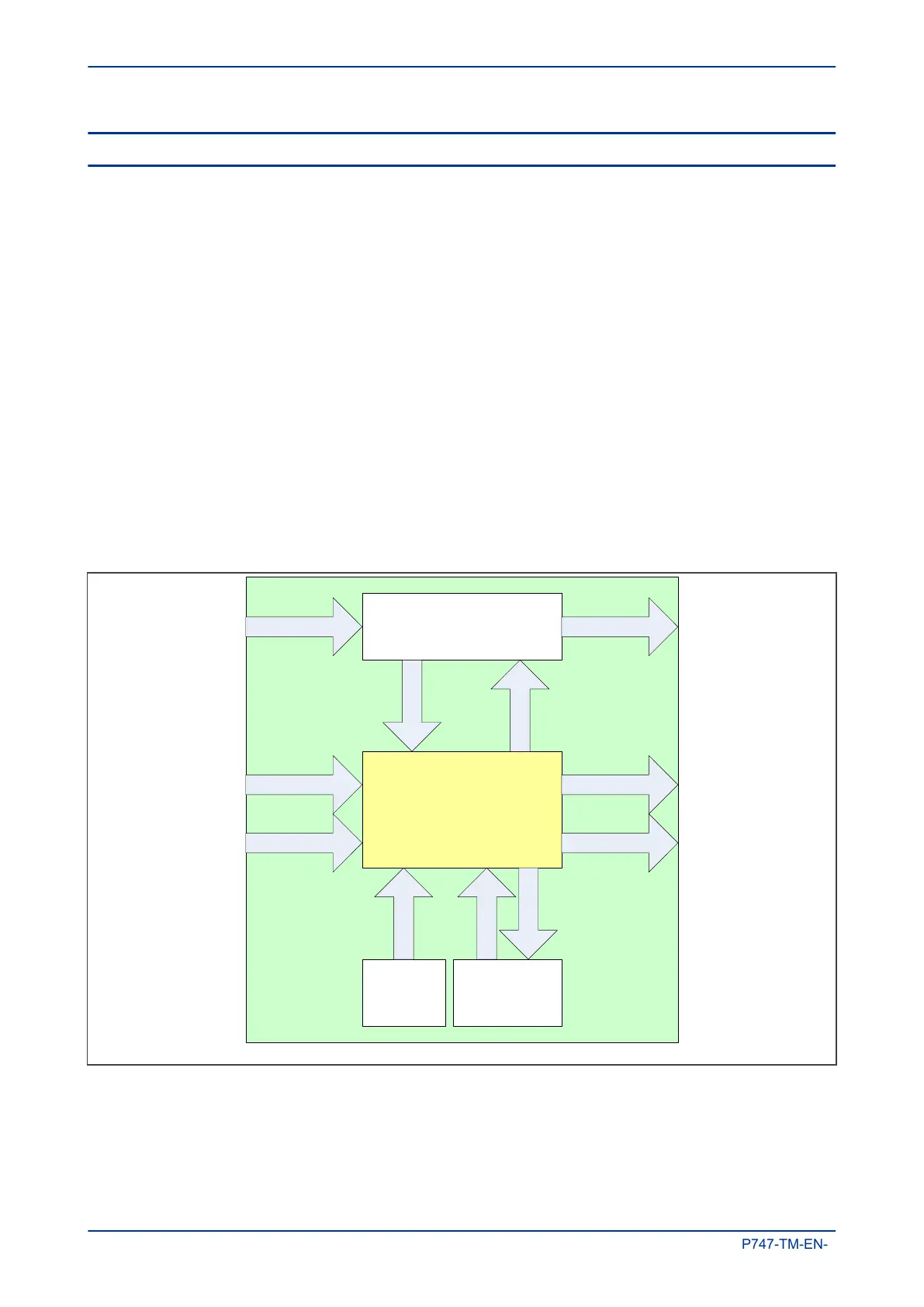
The following diagram shows how the scheme logic interacts with the rest of the IED.
V02011
PSL and FSL
Protection functions
S
L
i
n
p
u
t
s
S
L
o
u
t
p
u
t
s
Opto-inputs Programmable LEDs
Output relaysFunction keys
G
o
o
s
e
i
n
p
u
t
s
Control input
m
odule
G
o
o
s
e
o
u
t
p
u
t
s
Ethernet
p
rocessing module
Fixed LEDs
C
o
n
t
r
o
l
i
n
p
u
t
s
Energising quantities
Figure 73: Scheme Logic Interfaces
The inputs to the scheme logic are:
● Opto-inputs: Optically-coupled logic inputs
● Function keys: Keys on the device (not on all models)
Chapter 12 - Scheme Logic MiCOM P747
314 P747-TM-EN-1

 Loading...


