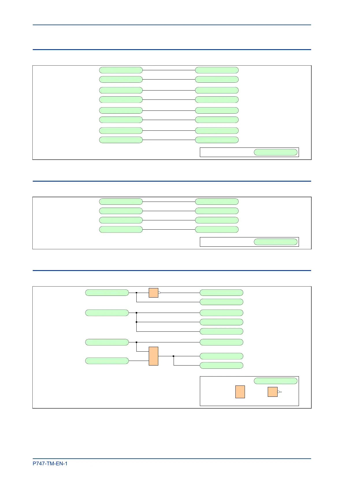
4.5 LED MAPPINGS
Trip Command Out LED1 Red
V02021
Key: External DDB Signal
Any Start LED1 Grn
CB Open 3 ph LED2 Red
CB Closed 3 ph LED2 Grn
AR In Progress LED3 Red
Successful Close LED3 Grn
AR Lockout LED4 Red
AR In Service LED4 Grn
Figure 84: LED Mappings
4.6 CONTROL INPUT MAPPINGS
Control Input 1 Reset Lockout
V02023
Key: External DDB Signal
Control Input 2 AR Auto Mode
Control Input 3 Telecontrol Mode
Control Input 4 AR LiveLine Mode
Figure 85: Control Input Mappings
4.7 FUNCTION KEY MAPPINGS
Function Key 1 Blk Rmt. CB Ops
V
02025
Key: External DDB Signal
OR gate 1
FnKey LED1 Red
Function Key 2 Init Trip CB
FnKey LED2 Red
FnKey LED2 Green
Function Key 3 Init Close CB
FnKey LED3 Red
FnKey LED3 Green
1
Close in Prog
NOT gate
Figure 86: Function Key Mappings
MiCOM P747 Chapter 12 - Scheme Logic
P747-TM-EN-1 325

 Loading...


