3 BOARD CONNECTIONS
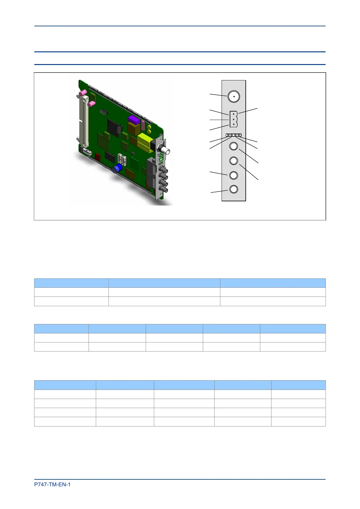
IRIG-B
Pin3
Link Fail
connector
Pin 2
P
in 1
Link channel
A
(green LED)
Activity channel
A (yellow LED)
Link channel B
(green LED)
Activity channel B
(yellow LED)
A
B
C
D
V01009
Figure 57: Board connectors
IRIG-B Connector
Available as a modulated or demodulated input. Centre connection, signal. Outer connection, Earth.
Link Fail Connector (Watchdog Relay)
Pin Closed Open
1-2 Link fail Channel 1 (A) Link ok Channel 1 (A)
2-3 Link fail Channel 2 (B) Link ok Channel 2 (B)
LEDs
LED Function On Off Flashing
Green Link Link ok Link broken
Yellow Activity SHP running PRP, RSTP or DHP traffic
Optical Fibre Connectors
Uses 1300 nm multi mode 100BaseFx and ST connectors.
Connector DHP RSTP SHP PRP
A RXA RX1 RS RXA
B TXA TX1 ES TXA
C RXB RX2 RP RXB
D TXB TX2 EP TXB
MiCOM P747 Chapter 8 - Redundant Ethernet
P747-TM-EN-1 243

 Loading...


