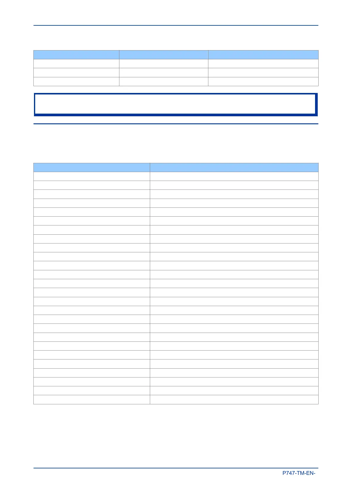
Case width (TE) Case width (mm) Case width (inches)
40TE 203.2 8
60TE 304.8 12
80TE 406.4 16
Note:
Due to the number of required input modules, the P747 only comes in an 80TE case
3.2 LIST OF BOARDS
The product's hardware consists of several modules drawn from a standard range. The exact specification
and number of hardware modules depends on the model number and variant. Depending on the exact
model, the product in question will use a selection of the following boards.
Board Use
Main Processor board Main Processor board – with support for function keys
Power supply board 24/54V DC Power supply input. Accepts DC voltage between 24V and 54V
Power supply board - 48/125V DC Power supply input. Accepts DC voltage between 48V and 125V
Power supply board 110/250V DC Power supply input. Accepts DC voltage between 110V and 125V
Transformer board Contains the voltage and current transformers
Input board Contains the A/D conversion circuitry
Input board with opto-inputs Contains the A/D conversion circuitry + 8 digital opto-inputs
IRIG-B board - modulated Interface board for modulated IRIG-B timing signal
IRIG-B - demodulated input Interface board for demodulated IRIG-B timing signal
Fibre board Interface board for fibre-based RS485 connection
Fibre + IRIG-B Interface board for fibre-based RS485 connection + demodulated IRIG-B
2nd rear communications board Interface board for RS232 / RS485 connections
2nd rear communications board with IRIG-B input Interface board for RS232 / RS485 + IRIG-B connections
100MhZ Ethernet board Standard 100MHz Ethernet board for LAN connection (fibre + copper)
100MhZ Ethernet board with modulated IRIG-B Standard 100MHz Ethernet board (fibre / copper) + modulated IRIG-B
100MhZ Ethernet board with demodulated IRIG-B Standard 100MHz Ethernet board (fibre / copper)+ demodulated IRIG-B
Redundant Ethernet SHP+ modulated IRIG-B Redundant SHP Ethernet board (2 fibre ports) + modulated IRIG-B input
Redundant Ethernet SHP + demodulated IRIG-B Redundant SHP Ethernet board (2 fibre ports) + demodulated IRIG-B input
Redundant Ethernet RSTP + modulated IRIG-B Redundant RSTP Ethernet board (2 fibre ports) + modulated IRIG-B input
Redundant Ethernet RSTP+ demodulated IRIG-B Redundant RSTP Ethernet board (2 fibre ports) + demodulated IRIG-B input
Redundant Ethernet DHP+ modulated IRIG-B Redundant DHP Ethernet board (2 fibre ports) + modulated IRIG-B input
Redundant Ethernet DHP+ demodulated IRIG-B Redundant DHP Ethernet board (2 fibre ports) + demodulated IRIG-B input
Redundant Ethernet PRP+ modulated IRIG-B Redundant PRP Ethernet board (2 fibre ports) + modulated IRIG-B input
Redundant Ethernet PRP+ demodulated IRIG-B Redundant PRP Ethernet board (2 fibre ports) + demodulated IRIG-B input
Output relay output board (8 outputs) Standard output relay board with 8 outputs
Combined coprocessor/opto-input board To provide extra processing power and extra opto-inputs
Chapter 3 - Hardware Design MiCOM P747
28 P747-TM-EN-1

 Loading...


