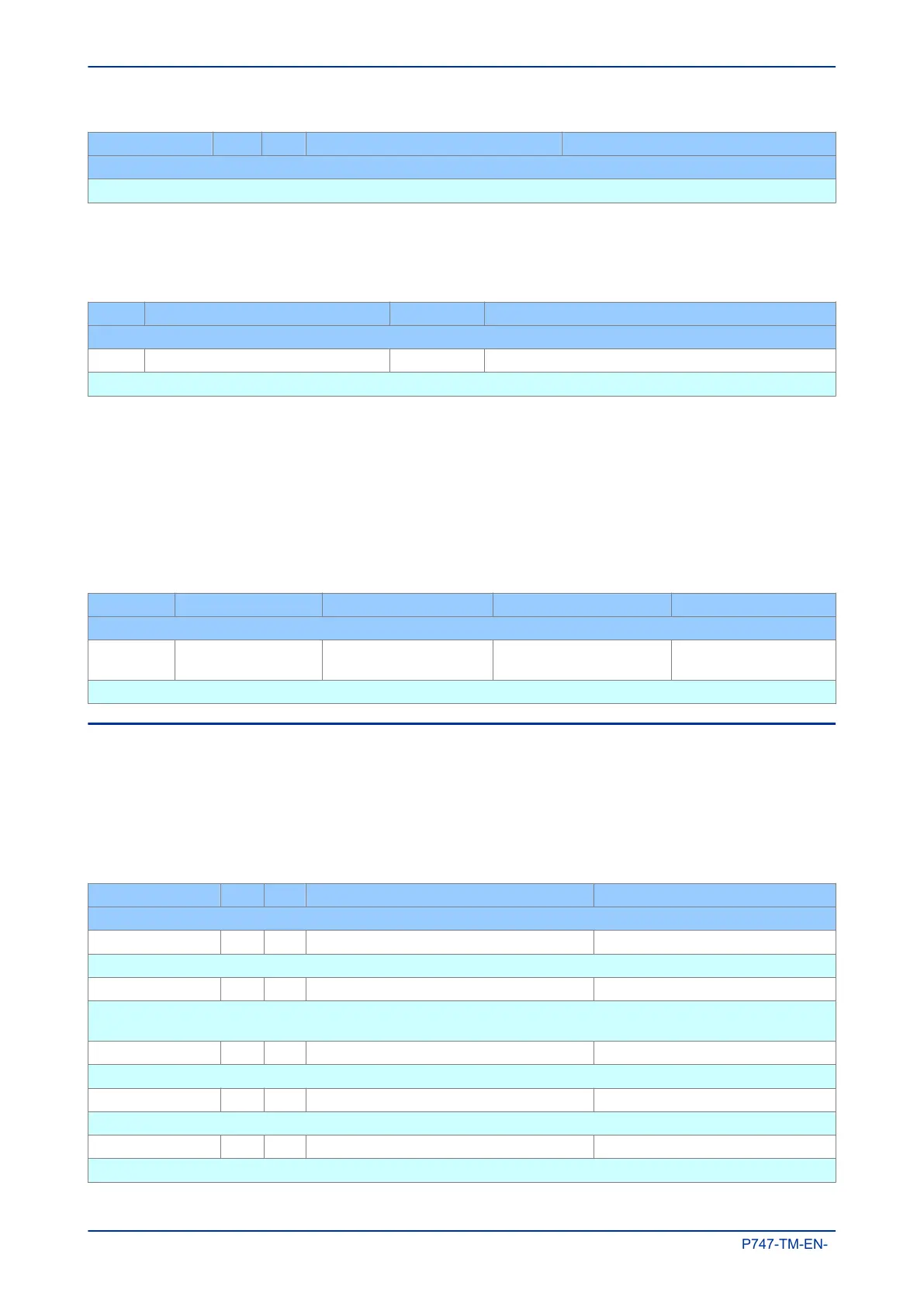
Courier Text Col Row Default Setting Available Options
Description
This setting defines the label for output relay 32
5.4.2 OUTPUT RELAY DDB SIGNALS
The output relays are associated with DDB signals. The default assignments are provided, but you can
configure these in the O/P LABELS
column if required.
Ordinal Signal Name Use Unique ID
Description
0 - 31 Output R1 Not Used – Output R31 Not Used Output relay DDB_OUTPUT_RELAY_1 - DDB_OUTPUT_RELAY_31
These DDB signals are connected to their respective output relay contacts
5.4.3 OUTPUT RELAY CONDITIONERS
When driving an output relay, the driving signal has to first be conditioned. We need to define certain
properties such as, pickup time, dropoff time, dwell and whether it is a pulsed or latched output. This is all
defined in the PSL Editor, which is described in the Setting Applications Software (on page
293) chapter.
A different set of DDB signals is provided for the purposes of connecting signals such as trip and start
commands and alarms, if these signals are to drive the output relays. The names of these DDB signals are
shown below.
Ordinal Signal Name Source Type Response
Description
128 to 159
Relay Conditioner 1 to
32
Programmable Scheme
Logic
Output Conditioner No Response
DDB signals for relay conditioners 1 to 32
5.5 CONTROL INPUTS
The control inputs are software switches, which can be set or reset locally or remotely. These inputs can be
used to trigger any PSL function to which they are connected. There are three setting columns associated
with the control inputs.
5.5.1 CONTROL INPUT SETTINGS
Courier Text Col Row Default Setting Available Options
Description
CONTROL INPUTS 12 00
This column contains settings for the type of control input
Ctrl I/P Status 12 01 Binary flag: 0 = Reset, 1 = Set
This cell sets or resets the first batch of 32 Control Inputs by scrolling and changing the status of selected bits.
Alternatively, each of the 32 Control inputs can be set and reset using the individual Control Input cells.
Control Input 1 12 02 No Operation 0 = No Operation, 1 = Set , 2 = Reset
This command sets or resets Control Input 1
Control Input 2 12 03 No Operation 0 = No Operation, 1 = Set , 2 = Reset
This command sets or resets Control Input 2
Control Input 3 12 04 No Operation 0 = No Operation, 1 = Set , 2 = Reset
This command sets or resets Control Input 3
Chapter 6 - Monitoring and Control MiCOM P747
180 P747-TM-EN-1

 Loading...


