Main Processor Board
Analogue to Digital Resolution 21 bit
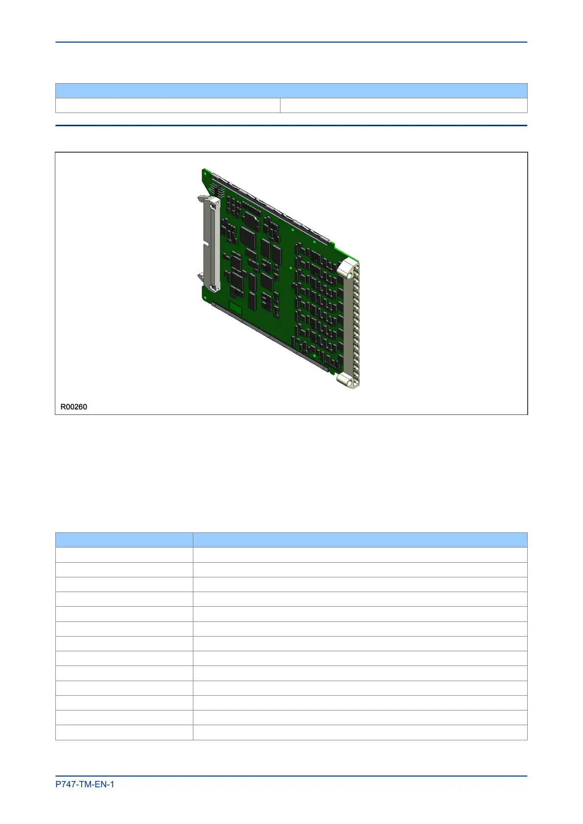
6.4 COMBINED COPROCESSOR AND ISOLATED INPUT BOARD
Figure 9: Combined coprocessor and isolated digital input board
This board has a coprocessor section and an isolated digital input section.
The coprocessor section is based around a floating point, 32-bit Digital Signal Processor (DSP) with 1 MB
SRAM. The coprocessor is used to speed up calculations for complex algorithms.
The input section is used to convert the analogue signals delivered by the current and voltage transformers
into digital quantities used by the IED. This board has eight isolated digital inputs with associated noise
filtering and buffering. The terminal numbers of the isolated digital inputs are as follows.
Terminal Number Isolated digital input
Terminal 1 Isolated digital input 1 -ve
Terminal 2 Isolated digital input 1 +ve
Terminal 3 Isolated digital input 2 -ve
Terminal 4 Isolated digital input 2 +ve
Terminal 5 Isolated digital input 3 -ve
Terminal 6 Isolated digital input 3 +ve
Terminal 7 Isolated digital input 4 -ve
Terminal 8 Isolated digital input 4 +ve
Terminal 9 Isolated digital input 5 -ve
Terminal 10 Isolated digital input 5 +ve
Terminal 11 Isolated digital input 6 -ve
Terminal 12 Isolated digital input 6 +ve
Terminal 13 Isolated digital input 7 –ve
MiCOM P747 Chapter 3 - Hardware Design
P747-TM-EN-1 37

 Loading...


