2.5.1 REPLACING THE MAIN PROCESSOR BOARD
The main processor board is situated in the front panel. This board contains application-specific settings in
its non-volatile memory. You may wish to take a backup copy of these settings. This could save time in the
re-commissioning process.
To replace the main processor board:
1.
Remove front panel.
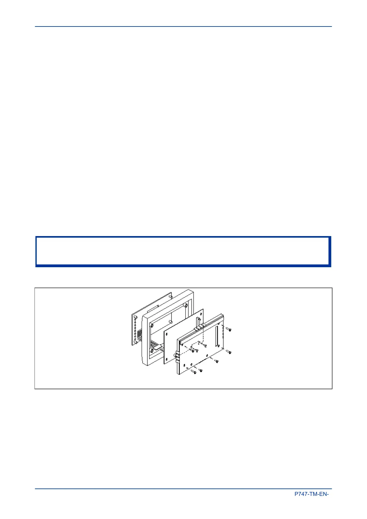
2. Place the front panel with the user interface face down and remove the six screws from the metallic
screen, as shown in the figure below. Remove the metal plate.
3. Remove the two screws either side of the rear of the battery compartment recess. These are the
screws that hold the main processor board in position.
4. Carefully disconnect the ribbon cable. Take care as this could easily be damaged by excessive
twisting.
5. Replace the main processor board
6. Reassemble the front panel using the reverse procedure. Make sure the ribbon cable is reconnected
to the main processor board and that all eight screws are refitted.
7. Refit the front panel.
8. Refit and close the access covers then press the hinge assistance T-pieces so they click back into the
front panel moulding.
9. Once the unit has been reassembled, carry out the standard commissioning procedure as defined in
the Commissioning chapter.
Note:
After replacing the main processor board, all the settings required for the application need to be re-entered. This may
be done either manually or by downloading a settings file.
Figure 97: Front panel assembly
2.5.2 REPLACEMENT OF COMMUNICATIONS BOARDS
Most products will have at least one communications board of some sort fitted. There are several different
boards available offering various functionality, depending on the application. Some products may even be
fitted two boards of different types.
Chapter 15 - Maintenance and Troubleshooting MiCOM P747
374 P747-TM-EN-1

 Loading...


