The products in the Px40 series typically contain two sub-assemblies:
● The power supply assembly comprising:
▪
A power supply board
▪ An output relay board
● The input module comprising:
▪ One or more transformer boards, which contains the voltage and current transformers (partially
or fully populated)
▪ One or more input boards
▪ Metal protective covers for EM (electromagnetic) shielding
The input module is pre-assembled and is therefore assigned a GN number, whereas the power supply
module is assembled at production stage and does not therefore have an individual part number.
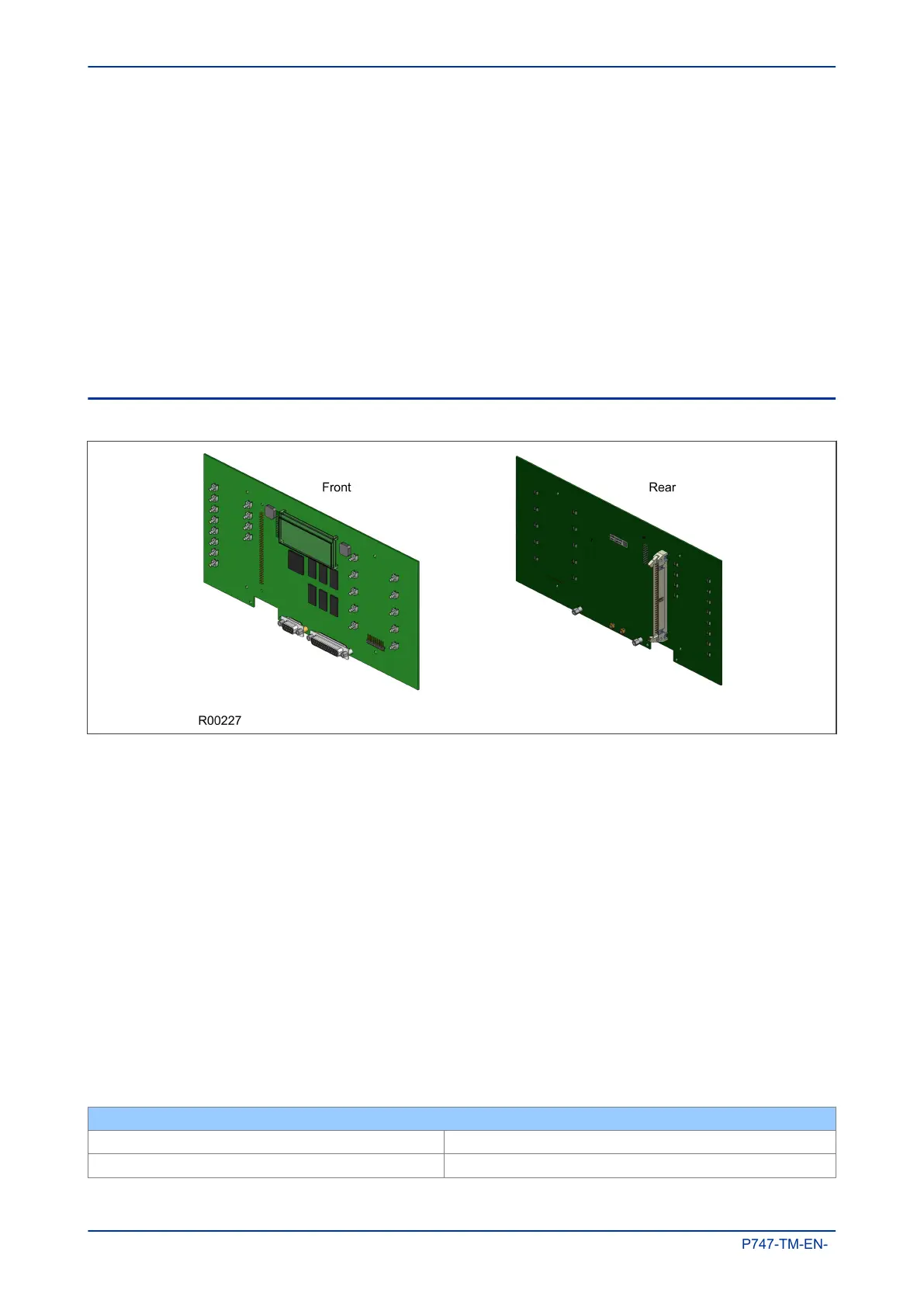
6.3 MAIN PROCESSOR BOARD
Figure 8: Main processor board
The main processor board is based around a floating point, 32-bit Digital Signal Processor (DSP). It performs
all calculations and controls the operation of all other modules in the IED, including the data communication
and user interfaces. This is the only board that does not fit into one of the slots. It resides in the front panel
and connects to the rest of the system using an internal ribbon cable.
The LCD and LEDs are mounted on the processor board along with the front panel communication ports. All
serial communication is handled using a Field Programmable Gate Array (FPGA).
The memory on the main processor board is split into two categories: volatile and non-volatile. The volatile
memory is fast access SRAM, used by the processor to run the software and store data during calculations.
The non-volatile memory is sub-divided into two groups:
● Flash memory to store software code, text and configuration data including the present setting values.
● Battery-backed SRAM to store disturbance, event, fault and maintenance record data.
There are two board types available depending on the size of the case:
● For models in 40TE cases
● For models in 60TE cases and larger
Main Processor Board
Sampling Rate 1200 Hz with frequency range of 46 to 54 Hz
Analogue to Digital Conversion 16 bit
Chapter 3 - Hardware Design MiCOM P747
36 P747-TM-EN-1

 Loading...


