Note:
To speed up the procedure, you can enter the alarm viewer using the Read key and subsequently pressing the Clear
key. This goes straight to the fault record display. Press the Clear key again to move straight to the alarm reset
prompt, then press the Clear key again to clear all alarms.
2.7 MENU STRUCTURE
Settings, commands, records and measurements are stored in a local database inside the IED. When using
the Human Machine Interface (HMI) it is convenient to visualise the menu navigation system as a table.
Each item in the menu is known as a cell, which is accessed by reference to a column and row address.
Each column and row is assigned a 2-digit hexadecimal numbers, resulting in a unique 4-digit cell address
for every cell in the database. The main menu groups are allocated columns and the items within the groups
are allocated rows, meaning a particular item within a particular group is a cell.
Each column contains all related items, for example all of the disturbance recorder settings and records are
in the same column.
There are three types of cell:
● Settings: this is for parameters that can be set to different values
● Commands: this is for commands to be executed
● Data: this is for measurements and records to be viewed, which are not settable
Note:
Sometimes the term "Setting" is used generically to describe all of the three types.
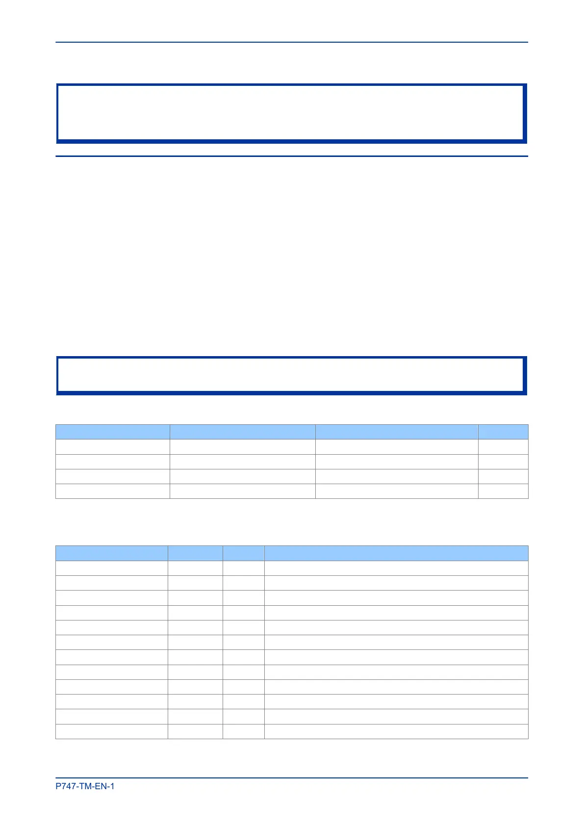
The table below, provides an example of the menu structure:
SYSTEM DATA (Col 00) VIEW RECORDS (Col 01) MEASUREMENTS 1 (Col 02) …
Language (Row 01) "Select Event [0...n]" (Row 01) IA Magnitude (Row 01) …
Password (Row 02) Menu Cell Ref (Row 02) IA Phase Angle (Row 02) …
Sys Fn Links Row 03) Time & Date (Row 03) IB Magnitude (Row 03) …
… … … …
It is convenient to specify all the settings in a single column, detailing the complete Courier address for each
setting. The above table may therefore be represented as follows:
Setting Column Row Description
SYSTEM DATA 00 00 First Column definition
Language (Row 01) 00 01 First setting within first column
Password (Row 02) 00 02 Second setting within first column
Sys Fn Links Row 03) 00 03 Third setting within first column
… … …
VIEW RECORDS 01 00 Second Column definition
Select Event [0...n] 01 01 First setting within second column
Menu Cell Ref 01 02 Second setting within second column
Time & Date 01 03 Third setting within second column
… … …
MEASUREMENTS 1 02 00 Third Column definition
IA Magnitude 02 01 First setting within third column
MiCOM P747 Chapter 4 - Configuration
P747-TM-EN-1 63

 Loading...


