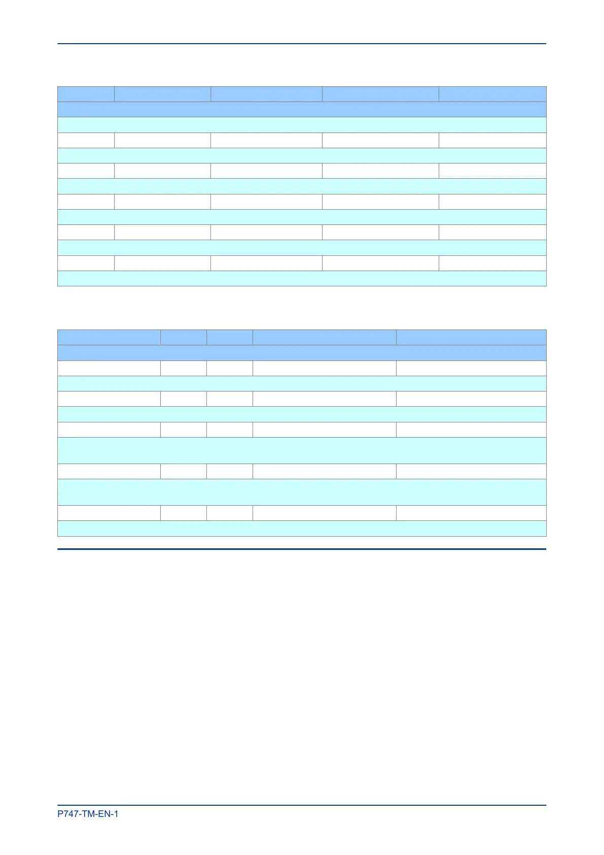
Ordinal Signal Name Source Type Response
Description
DDB signal indicates that Function key 5 is active
325 Function Key 6 Software Function Key Protection event
DDB signal indicates that Function key 6 is active
326 Function Key 7 Software Function Key Protection event
DDB signal indicates that Function key 7 is active
327 Function Key 8 Software Function Key Protection event
DDB signal indicates that Function key 8 is active
328 Function Key 9 Software Function Key Protection event
DDB signal indicates that Function key 9 is active
329 Function Key 10 Software Function Key Protection event
DDB signal indicates that Function key 10 is active
5.1.2 FUNCTION KEY SETTINGS
Menu Text Col Row Default Setting Available Options
Description
FUNCTION KEYS 17 00
This column contains the function key definitions
Fn Key Status 17 01 0 8-bit binary string
This cell displays the status of each function key
Fn Key 1 - 10 17 02 - 1D Unlocked Disable, Lock or Unlock
This setting activates function key 1. The ‘Lock’ setting allows a function key, which is in toggle mode, to be locked in its
current active state.
Fn Key 1 - 10 Mode 17 03 - 1E Toggled Toggle or Normal
This setting sets the function key mode. In ‘Toggle’ mode, a single key press set sand latches the function key output to
‘high’ or ‘low’ in the PSL. In ‘Normal’ mode the function key output remains high as long as key is pressed.
Fn Key 1 - 10 Label 17 04 - 1F Function Key 1 16-character text string
This setting lets you change the function key text to something more suitable for the application.
5.2 LEDS
Depending on the model, different numbers of LEDs are used. Some are fixed function LEDs, some are
programmable, and for devices with function keys there are LEDs associated with each function key.
5.2.1 FIXED FUNCTION LEDS
Four fixed-function LEDs on the left-hand side of the front panel indicate the following conditions.
● Trip (Red) switches ON when the IED issues a trip signal. It is reset when the associated fault record
is cleared from the front display. Also the trip LED can be configured as self-resetting.
● Alarm (Yellow) flashes when the IED registers an alarm. This may be triggered by a fault, event or
maintenance record. The LED flashes until the alarms have been accepted (read), then changes to
constantly ON. When the alarms are cleared, the LED switches OFF.
● Out of service (Yellow) is ON when the IED's protection is unavailable.
● Healthy (Green) is ON when the IED is in correct working order, and should be ON at all times. It goes
OFF if the unit’s self-tests show there is an error in the hardware or software. The state of the healthy
LED is reflected by the watchdog contacts at the back of the unit.
MiCOM P747 Chapter 6 - Monitoring and Control
P747-TM-EN-1 169

 Loading...


