5 I/O FUNCTIONS
5.1 FUNCTION KEYS
For many models, a number of programmable function keys are available. This allows you to assign function
keys to control functionality via the programmable scheme logic (PSL). Each function key is associated with
a programmable tri-colour LED, which you can program to give the desired indication on activation of the
function key.
These function keys can be used to trigger any function that they are connected to as part of the PSL. The
function key commands are found in the FUNCTION KEYS column.
Each function key is associated with a DDB signal as shown in the DDB table. You can map these DDB
signals to any function available in the PSL.
The Fn Key Status cell displays the status (energised or de-energised) of the function keys by means of a
binary string, where each bit represents a function key starting with bit 0 for function key 1.
Each function key has three settings associated with it, as shown:
● Fn Key (n), which enables or disables the function key
● Fn Key (n) Mode, which allows you to configure the key as toggled or normal
● Fn Key (n) label, which allows you to define the function key text that is displayed
The Fn Key (n)
cell is used to enable (unlock) or disable the function key signals in PSL. The Lock setting
has been provided to prevent further activation on subsequent key presses. This allows function keys that
are set to Toggled mode and their DDB signal active ‘high’, to be locked in their active state therefore
preventing any further key presses from deactivating the associated function. Locking a function key that is
set to the “Normal” mode causes the associated DDB signals to be permanently off. This safety feature
prevents any inadvertent function key presses from activating or deactivating critical functions.
When the Fn Key (n) Mode cell is set to Toggle, the function key DDB signal output will remain in the set
state until a reset command is given. In the Normal mode, the function key DDB signal will remain energised
for as long as the function key is pressed and will then reset automatically. In this mode, a minimum pulse
duration can be programmed by adding a minimum pulse timer to the function key DDB output signal.
The Fn Key Label cell makes it possible to change the text associated with each individual function key.
This text will be displayed when a function key is accessed in the function key menu, or it can be displayed in
the PSL.
The status of all function keys are recorded in non-volatile memory. In case of auxiliary supply interruption
their status will be maintained.
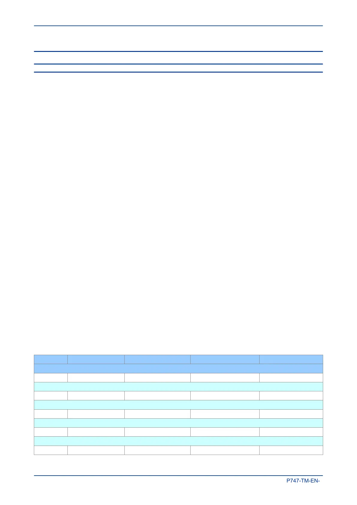
5.1.1 FUNCTION KEY DDB SIGNALS
Ordinal Signal Name Source Type Response
Description
320 Function Key 1 Software Function Key Protection event
DDB signal indicates that Function key 1 is active
321 Function Key 2 Software Function Key Protection event
DDB signal indicates that Function key 2 is active
322 Function Key 3 Software Function Key Protection event
DDB signal indicates that Function key 3 is active
323 Function Key 4 Software Function Key Protection event
DDB signal indicates that Function key 4 is active
324 Function Key 5 Software Function Key Protection event
Chapter 6 - Monitoring and Control MiCOM P747
168 P747-TM-EN-1

 Loading...


