Opto-isolated inputs
The other function of the input board is to read in the digital inputs. As with the analogue inputs, the digital
inputs must be electrically isolated from the power system. This is achieved by means of the 8 on-board
optical isolators for connection of up to 8 digital signals. The digital signals are passed through an optional
noise filter before being buffered and presented to the unit’s processing boards in the form of a parallel data
bus.
This selectable filtering allows the use of a pre-set filter of ½ cycle which renders the input immune to
induced power-system noise on the wiring. Although this method is secure it can be slow, particularly for
inter-tripping. This can be improved by switching off the ½ cycle filter in which case one of the following
methods to reduce ac noise should be considered.
● Use double pole switching on the input
● Use screened twisted cable on the input circuit.
The opto-isolated logic inputs can be programmed for the nominal battery voltage of the circuit for which they
are a part, allowing different voltages for different circuits such as signalling and tripping. They can also be
programmed to 60% - 80% or 50% - 70% pickup to dropoff ratio of the nominal battery voltage in order to
satisfy different operating constraints.
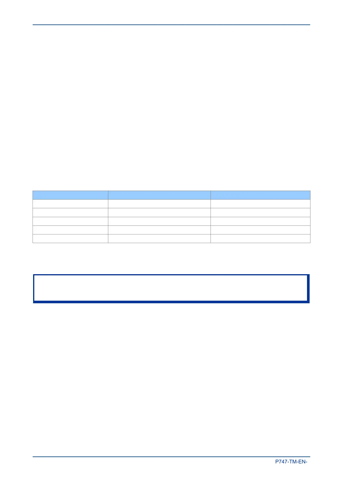
The threshold levels are as follows:
Nominal Battery voltage Logic levels: 60-80% DO/PU Logic Levels: 50-70% DO/PU
24/27 V Logic 0 < 16.2 V : Logic 1 > 19.2 V Logic 0 <12.0 V : Logic 1 > 16.8
30/34 Logic 0 < 20.4 V : Logic 1 > 24.0 V Logic 0 < 15.0 V : Logic 1 > 21.0 V
48/54 Logic 0 < 32.4 V : Logic 1 > 38.4 V Logic 0 < 24.0 V : Logic 1 > 33.6 V
110/125 Logic 0 < 75.0 V : Logic 1 > 88.0 V Logic 0 < 55.0 V : Logic 1 > 77.0 V
220/250 Logic 0 < 150 V : Logic 1 > 176.0 V Logic 0 < 110 V : Logic 1 > 154.0 V
The lower value eliminates fleeting pickups that may occur during a battery earth fault, when stray
capacitance may present up to 50% of battery voltage across an input.
Note:
The opto-input circuitry can be provided without the A/D circuitry as a separate board, which can provide
supplementary opto-inputs.
Chapter 3 - Hardware Design MiCOM P747
44 P747-TM-EN-1

 Loading...


