1-2 F650 Digital Bay Controller GE Multilin
1.1 IMPORTANT PROCEDURES 1 GETTING STARTED
1
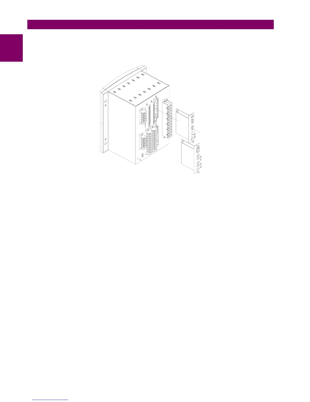
Communication boards are installed on the rear of the unit, the upper port being reserved for the asynchronous
communications board and CAN, and the lower port for the ETHERNET board in any of its configurations.
Figure 1–2: MODULE WITHDRAWAL/INSERTION
Before performing any of these actions, control power must be removed from the relay and all the relay rear terminals
must be potential free. A grounded antistatic wristband must be used when manipulating the module in order to avoid
electrostatic discharges that may cause damage to the electronic components.
WITHDRAWAL: Loose the small screws that keep the faceplate in place and extract the module.
INSERTION: Insert the module and press it firmly in the case, until it is completely fixed. After this, bolt the faceplate
screws and replace the control power. Check that the relay is fully operative.
GE Multilin will not be responsible for any damage in the relay, connected equipment or personnel whenever this safety
rules are not followed.

 Loading...


