9-14 F650 Digital Bay Controller GE Multilin
9.12 DIRECTIONAL ELEMENTS (67P, 67N, 67G, 67SG) 9 COMMISSIONING
9
9.12DIRECTIONAL ELEMENTS (67P, 67N, 67G, 67SG)
In order to test directional units in the relay, instantaneous trips will be commanded.
Two points will be tested, per phase, test element.
The factory default configuration of the relay makes the overcurrent elements be supervised by directional units. This way,
if the directional element is enabled and detects the fault in the block direction, then the overcurrent unit will not operate. If
the directional element is not enabled or if it is enabled and it detects a fault in a trip direction, then the overcurrent unit will
operate if the set current level is exceeded.
9.12.1 67P ELEMENT
Activate only protection elements 50PH and 67P and set the relay as follows:
Configure one of the outputs to be activated only by unit 50PH.
Apply the following tests:
9.12.2 67N ELEMENT
Activate only protection elements 50N and 67N and set the relay as follows:
Configure one of the outputs to be activated only by unit 50G.
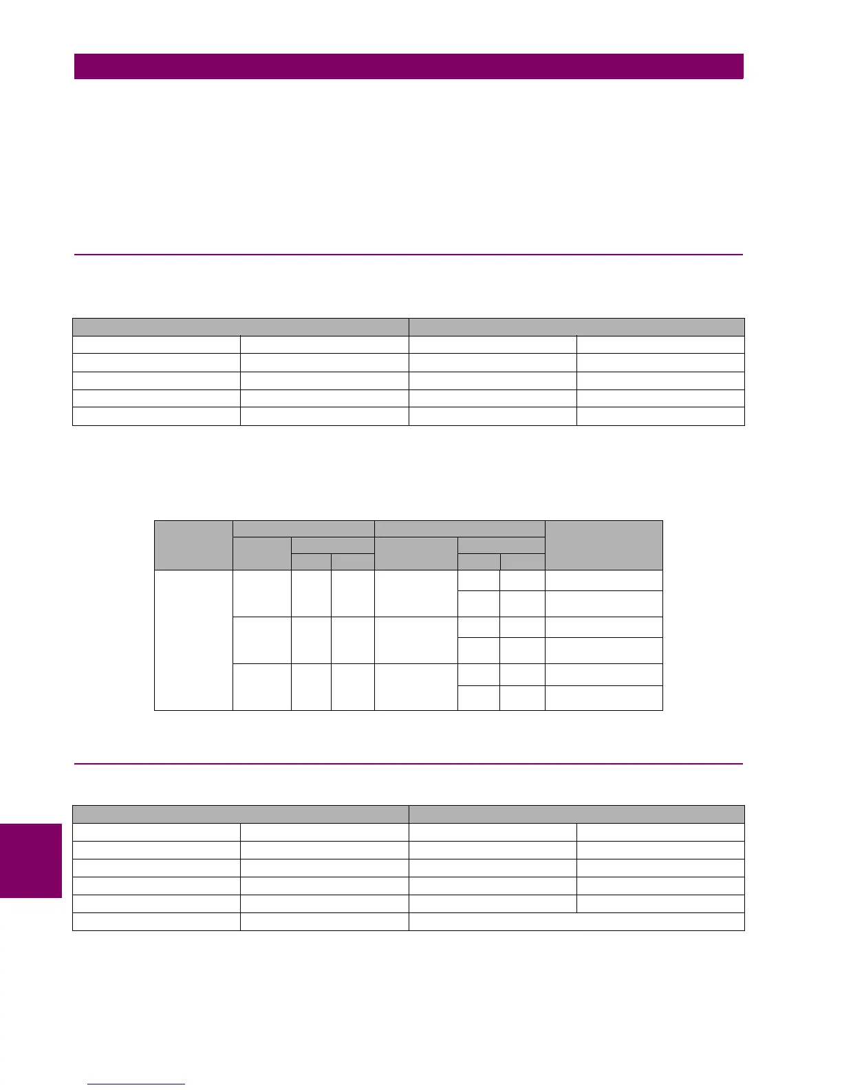
67P Settings 50PH Settings
Function ENABLED Function ENABLED
MTA 45 Deg Input PHASOR (DFT)
Direction FORWARD Pickup Level 0.50 A
Block Logic PERMISSION Trip Delay 0.30
Pol V Threshold 30 V Reset Delay 0.00
ELEMENTS PHASE UNDER TEST POLARIZATION PHASE ELEMENT TRIP
CHANNE
L
MAGNITUDE CHANNEL MAGNITUDE
MOD ARG MOD ARG
50PH/67P IA 2 A 0º VIII 60 V 0º NO
60 V 180º YES
IB 2 A 0º VI 60 V 0º NO
60 V 180º YES
IC 2 A 0º VII 60 V 0º NO
60 V 180º YES
67N Settings 50N Settings
Function ENABLED Function ENABLED
MTA -45 Deg Input PHASOR (DFT)
Direction FORWARD Pickup Level 0.50 A
Polarization VO Trip Delay 0.30
Block Logic PERMISSION Reset Delay 0.00
Pol V Threshold 10 V

 Loading...


