GE Multilin F650 Digital Bay Controller 5-131
5 SETPOINTS 5.8 RELAY CONFIGURATION
5
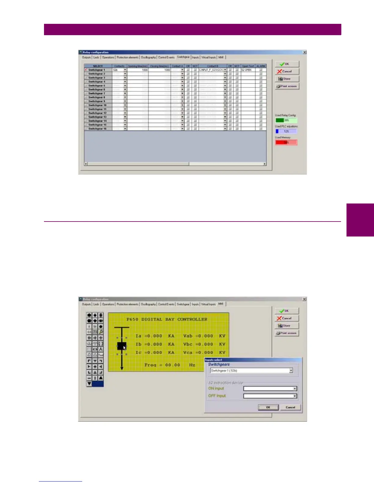
Figure 5–48: SWITCHGEAR CONFIGURATION
Note: when a switchgear device is only monitored (open init and closing init signals are not used), it is not possible to
distinguish between the fail to open or fail to close time, the time used to give an error 00 or 11 signal is the maximum of the
opening and closing time configured for that switchgear.
5.8.8 HMI (HUMAN-MACHINE INTERFACE)
This menu shows a scenario to draw a simplified one-line diagram of a bay in a feeder, line, transformer, etc. The menu
includes a library for power elements, metering elements, text and drawings.
For using the drawing toolbar elements, we must select the desired element with the mouse and then click on the yellow
area. The selected element will be moved to the screen on the selected spot (see ).
The graphic display can be used to configured switchgear elements, operations, metering values, date and time, etc. The
configured values will always be updated with the real status of the relay.
This functionality is only applicable to F650 units with graphical display (240x128pixels), and not for units with
alphanumerical display (20x4 characters).
Figure 5–49: HMI CONFIGURATION

 Loading...


