5-114 F650 Digital Bay Controller GE Multilin
5.6 INPUTS/OUTPUTS 5 SETPOINTS
5
This works correctly in steady state. However, if the breaker trips, while it is opening, the V 52/a input signal can be
deactivated without this meaning that the circuit is not correct. This is due to the fact that the tripping relay, terminals F35-
F36, short circuits input V 52/a temporarily.
Therefore, if there is a trip signal, it is admitted that no signal will be detected during a period of 1 s to allow the breaker to
open, and reopen the tripping relay F35-F36.
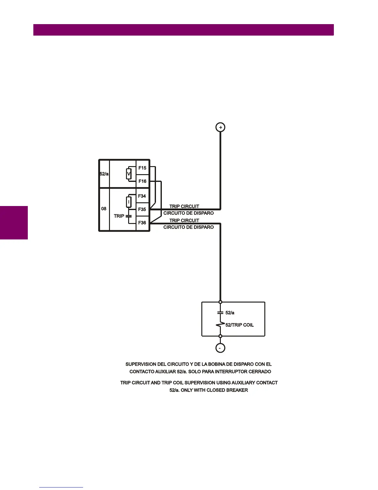
shows the possibility of monitoring the circuit only when the breaker is closed. In this case resistance R will not
be used, but it must be observed in the unit logic, that the corresponding signal CONT IP_F_CC16
(SUP_COIL2) will be activated showing a failure when the breaker is open, and therefore it will be required to
supervise the continuity failure signaling by the breaker status information.
Figure 5–35: TRIP CIRCUIT AND TRIP COIL SUPERVISION USING AUXILIARY CONTACT 52/A. ONLY WITH
CLOSED BREAKER (A6631F5)

 Loading...


