GE Multilin F650 Digital Bay Controller 5-53
5 SETPOINTS 5.4 PROTECTION ELEMENTS
5
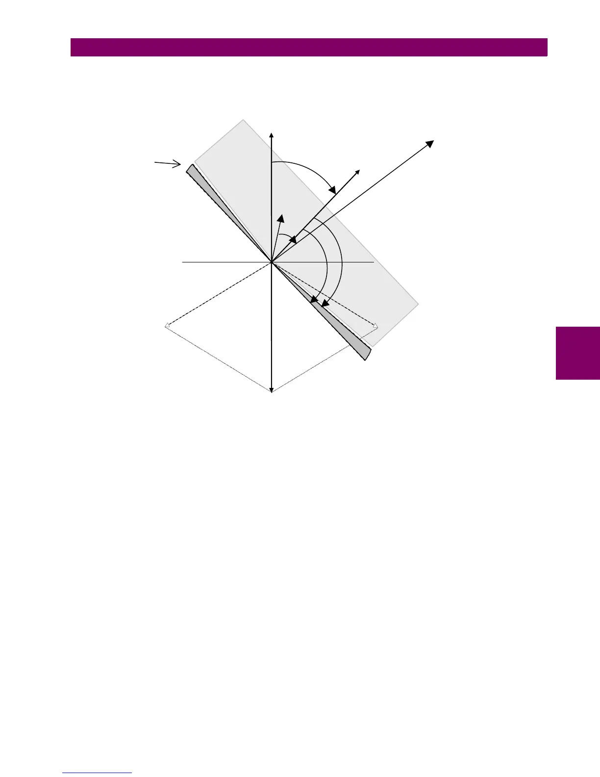
Figure 5–12: shows the Operation of the directional unit for a Phase A to Ground fault, where the Phase A current grows in
magnitude and is delayed with respect to its voltage by an angle similar to the protected line, while Va voltage decreases or
can even disappear if the fault is close and the fault resistance is very low.
Figure 5–12: VOLTAGE POLARIZATION
The voltage polarization algorithm uses –Vn, -(Va+Vb+Vc) = -3·V
0
, as a substitute for the faulted phase voltage. This
magnitude can be rotated by the desired angle to fix the MTA line and to define the operative semi plane of the relay,
following the rule that positive angles are in counter clockwise direction. A typical setpoint is –45º, as shown on the figure.
The operative semi plane is delimited to +/- 85º of the MTA line. Every time the operation magnitude, In, is inside this semi
plane, the unit will consider that the direction is forward. If the Direction setpoint is set as Forward, the operation signal of
the neutral directional unit (NEUTRAL DIR OP) will be activated.
Minimum acceptable values, both for the polarization magnitude and the operation magnitude are as follows: minimum In
current for the unit to operate is 50 mA. Minimum polarization voltage for the unit to operate is set in the Polarization
Voltage Threshold setpoint. Minimum polarization current (Ip) is 5 mA.
The voltage polarized directional unit needs a typical time of 1 cycle (20ms @ 50Hz) to polarize. This time must be
considered when setpoint the overcurrent units with the Block Logic setpoint as Permission. In this situation it may occur,
especially in testing processes, that the relay produces a trip with counter direction faults when voltage and current are
applied at the same time starting from zero. As there is no previous polarization voltage, the overcurrent unit is ready to trip
under any overcurrent (as set in the Block Logic setpoint), while the directional unit will need a complete cycle to polarize
and give the correct direction. If the current is high enough to pickup the overcurrent unit and there is no set time delay, the
unit will trip before the directional unit blocks the trip. In cases where this situation is foreseen, it is recommended to
program the Block Logic setpoint as Block, or else to add a small time delay to the overcurrent unit to allow the directional
unit to polarize and block the trip.
Vb Vc
-3V0
3V0 = Va +Vb+Vc
-45º
Maximum
tor
ue an
le
Cone 5º
Forward
IA
Fault Ia
In
-85º = 90º - 5º cone
-90º

 Loading...


