GE Multilin F650 Digital Bay Controller 5-127
5 SETPOINTS 5.8 RELAY CONFIGURATION
5
5.8.5 OSCILLOGRAPHY
This menu is used for selecting the digital channels to be included in oscillography records, and the oscillo trigger signal. As
for the above-described setpoints, the trigger selection can be any of the signals provided by the relay or a logic
combination of these.
setpoints are described below:
• Select checkbox enables or disables a digital channel and the oscillography trigger.
• Name setpoint defines the name of the digital channel to be included in oscillography records.
• Source setpoint defines the source or signal to be recorded in that specific channel, which can be selected among all
the operands available in the signals menu.
• NOT checkbox inverts the enabled digital channel signal.
• OR checkbox to select a group of operands instead of a single one. The relay performs an OR of the signals, and its
output produces operation.
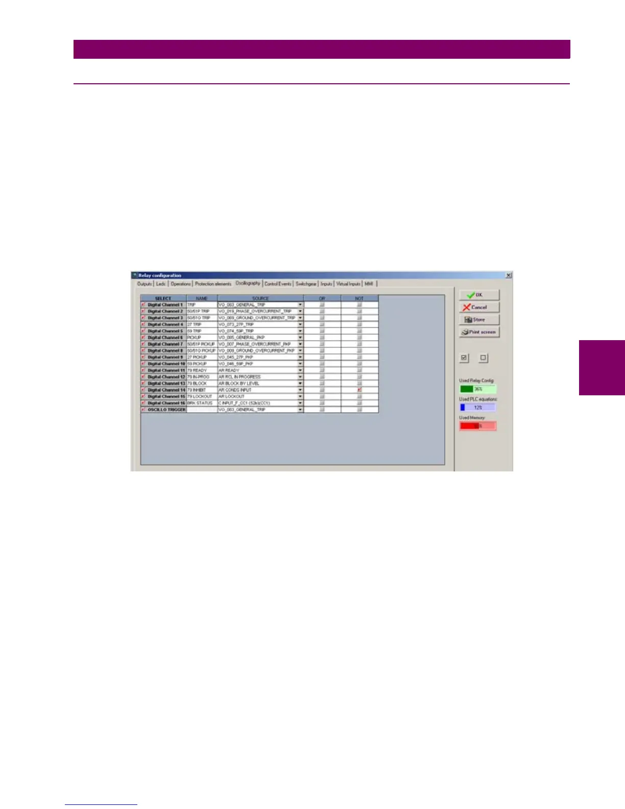
Figure 5–46: OSCILLOGRAPHY CONFIGURATION
NOTE This screen is used for the configuration of digital channels and oscillography trigger. The rest of parameters,
such as function enabling/disabling, sampling rate, number of oscillography files, etc. must be set on the
Setpoint > Product Setup > Oscillography menu.

 Loading...


