GE Multilin F650 Digital Bay Controller 6-11
6 ACTUAL VALUES 6.2 STATUS
6
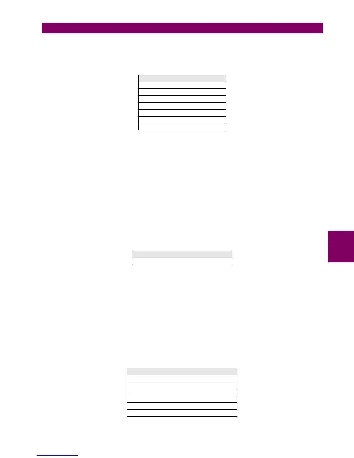
6.2.4.4 BREAKER FAILURE
This screen can be accessed at Actual> Status > Control Elements > Breaker Failure, and it includes the following
signaling LEDs for the breaker failure function:
Table 6–16: BREAKER FAILURE ACTUAL VALUES
BKR FAIL INITIATE External signal for breaker failure initiation. (configurable at Settings> Relay Configuration >
Protection Elements).
BKR FAIL NO CURRENT Signal for breaker failure without current
BKR FAIL SUPERVISION Signal for supervision level breaker failure (retrip)
BKR FAIL HISET Signal for high-level breaker failure
BKR FAIL LOWSET Signal for low-level breaker failure
INTERNAL ARC Signal for internal arc
BKR FAIL 2nd STEP Signal for Second level breaker failure (high and low)
6.2.4.5 VT FUSE FAILURE
This screen can be accessed at Actual> Status > Control Elements >VT Fuse Failure, and it includes only one LEDs for
the VT fuse failure function, indicating the activation of the unit.
Table 6–17: VT FUSE FAILURE ACTUAL VALUES
6.2.4.6 BROKEN CONDUCTOR
F650 units incorporate three Broken Conductor elements for special applications that may require different timing steps or
levels for alarm or trip purposes.
The green LED will light up when the pickup or trip (operation) of each of the three available functions is activated. The
three of them are identical and can be configured separately.
These functions compare the negative and positive sequence current levels per phase. If this magnitude exceeds a
programmable threshold and is maintained for a programmable time delay, a tripping output will be issued. If a pickup or
operation is produced, the corresponding LED in this screen will light up.
This screen can be accessed at Actual> Status > Control Elements > Broken Conductor, and it includes the following
signaling LEDs for the breaker failure function:
Table 6–18: TABLE 6-18 BROKEN CONDUCTOR ACTUAL VALUES
BREAKER FAILURE ACTUAL VALUES
BKR FAIL INITIATE
BKR FAIL NO CURRENT
BKR FAIL SUPERVISION
BKR FAIL HISET
BKR FAIL LOWSET
INTERNAL ARC
BKR FAIL 2nd STEP
VT FUSE FAILURE ACTUAL VALUES
VT FUSE FAILURE
BROKEN CONDUCTOR ACTUAL VALUES
BROKEN CONDUCT1 PKP
BROKEN CONDUCT1 OP
BROKEN CONDUCT2 PKP
BROKEN CONDUCT2 OP
BROKEN CONDUCT3 PKP
BROKEN CONDUCT3 OP

 Loading...


