5-56 F650 Digital Bay Controller GE Multilin
5.4 PROTECTION ELEMENTS 5 SETPOINTS
5
5.4.5 GROUND CURRENT
The F650 Ground Current menu incorporates the following overcurrent elements:
Ground time overcurrent (51G)
Ground instantaneous overcurrent (50G)
Ground directional unit (67G)
5.4.5.1 GROUND TIME DELAYED OVERCURRENT UNIT (51G)
51G unit is a ground time delayed overcurrent protection element. The ground current input quantity is measured from the
magnetic module ground input, terminals B9-B10, and it may be programmed as Fundamental phasor magnitude or total
waveform RMS magnitude as required by the application. The unit trip can be time delayed using a selectable curve. And it
incorporates a reset time selectable between instantaneous or linear.
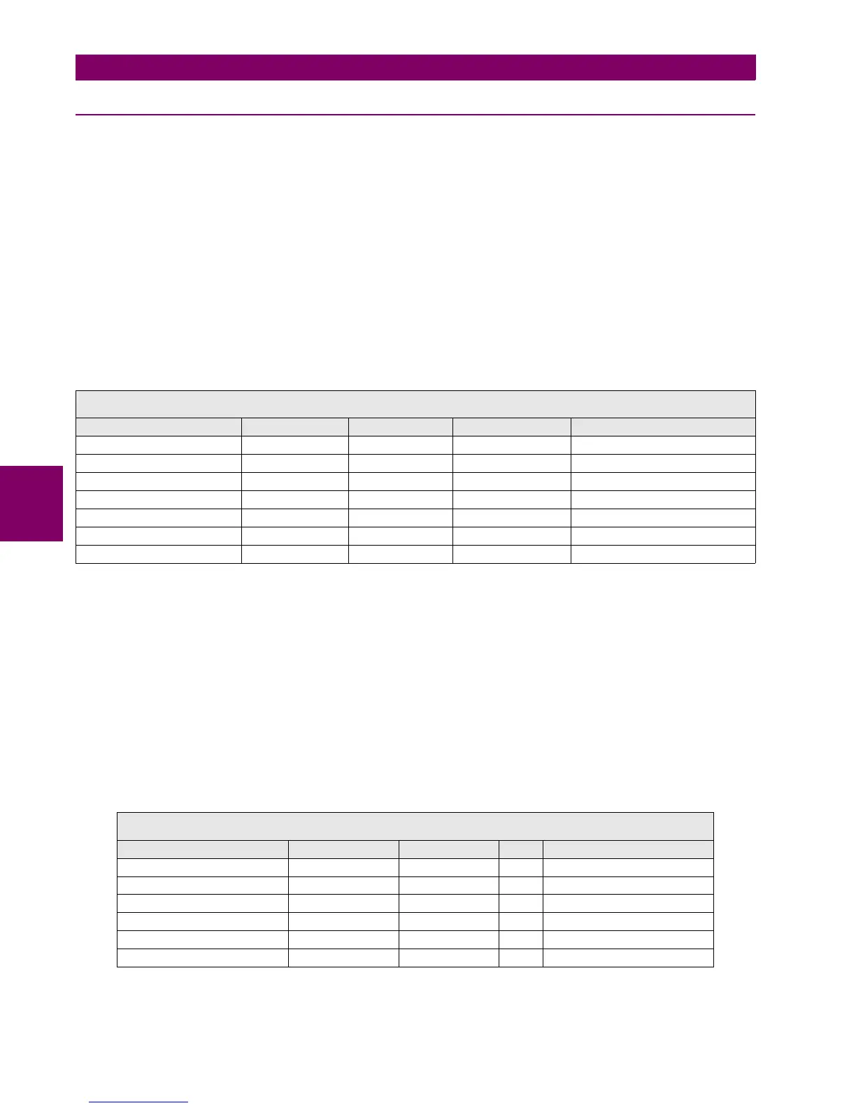
Table 5–49: 51G UNIT SETPOINTS
The snapshot event setpoint enables or disables the snapshot event generation for this unit.
5.4.5.2 GROUND INSTANTANEOUS OVERCURRENT UNIT (50G)
50G unit is a ground instantaneous overcurrent protection element, with a setpoint range from 0.05 A to 160 A, which can
also be time delayed, with a delay selectable between 0.00 and 900 seconds. The ground current input quantity is
measured from the transformers module ground input, and it may be programmed as Fundamental phasor magnitude or
total waveform RMS magnitude as required by the application. The unit incorporates a reset time selectable between 0 and
900 seconds, and a block input that resets the pickup and trip signals to 0. The unit outputs are the general pickup and trip
signals of the unit.
Table 5–50: 50G UNIT SETPOINTS
The snapshot event setpoint enables or disables the snapshot event generation for this unit.
SETPOINT > PROTECTION ELEMENTS > GROUND CURRENT > GROUND TOC
GROUND TOC 1> GROUND TOC 2 > GROUND TOC 3
SETPOINT DESCRIPTION NAME DEFAULT VALUE STEP RANGE
Function permission Function DISABLED N/A [DISABLED – ENABLED]
Input type Input PHASOR(DFT) N/A [PHASOR – RMS]
Pickup level Pickup Level 1.00 0.01 A [0.05 : 160.00]
Curve shape Curve IEEE Ext Inv N/A [See list of curves]
Time Dial TD Multiplier 1.00 0.01 s [0.00 : 900.00]
Reset type Reset INSTANTANEOUS N/A [INSTANTANEOUS – LINEAR]
Snapshot Event generation Snapshot Events ENABLED N/A [DISABLED – ENABLED]
SETPOINT > PROTECTION ELEMENTS > GROUND CURRENT > GROUND IOC
GROUND IOC 1> GROUND IOC 2 > GROUND IOC 3
SETPOINT DESCRIPTION NAME DEFAULT VALUE STEP RANGE
Function permission Function DISABLED N/A [DISABLED – ENABLED]
Input type Input PHASOR(DFT) N/A [PHASOR – RMS]
Pickup level Pickup Level 30.00 0.01 A [0.05 : 160.00]
Trip time Trip Delay 0.00 0.01 s [0.00 : 900.00]
Reset time Reset Delay 0.00 0.01 s [0.00 : 900.00]
Snapshot event generation Snapshot Events ENABLED N/A [DISABLED – ENABLED]

 Loading...


