GE Multilin F650 Digital Bay Controller 8-5
8 BOOTCODE AND FIRMWARE UPDATE 8.2 BOOT CODE UPDATE
8
8.2BOOT CODE UPDATE
Operating system update is performed using EnerVista F650 Setup. For this purpose, it is required that there is no
communication between the program and the relay, and that no configuration file is open.
In this case, menu option Upgrade Operating System will be enabled under the EnerVista F650 Setup Communication
menu.
During the operative system updating process, all the data stored in the relay will be lost, so it is required to save all
calibration, settings, oscillography, etc. from the relay before the upgrade. It is extremely important to save the relay
settings and calibration before continuing with the process. In this step of the updating process if the user do not want to
continue, click on the NO option and no change will be perform to the relay.
Figure 8–5: LOST DATA WARNING MESSAGE
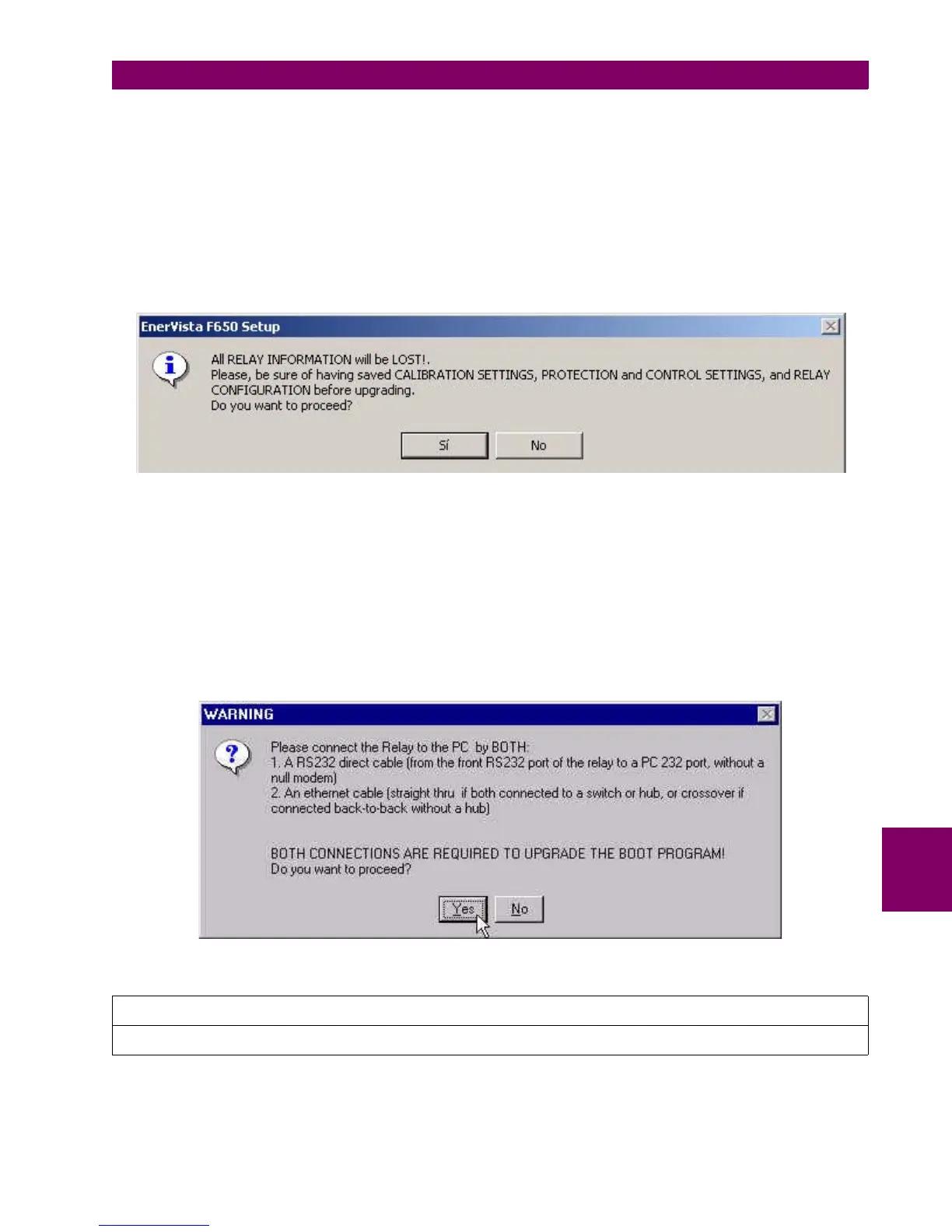
For upgrading the operative system, it is required to connect an RS232 cable to the front of the relay, and an Ethernet cable
to the rear port (COM3). The serial communication parameters will be the ones selected in the Communications >
Computer menu, where the COMX port (the port to be used in the upgrade) must be selected. As regards Ethernet
communication, if the upgrade is to be performed through a hub or switch, it is required to connect the relay to the hub or
switch through a direct 10/100 base T cable.
If the connection is made directly from the PC to the relay it is necessary to use a 10/100 Base T crossover cable. This last
connection will be obligatory for relays with Fiber Optic Ethernet, although it will not be necessary to change the internal
switch. During the upgrade, the system will show the following message indicating the procedure to be followed.
Figure 8–6: SERIAL AND ETHERNET CONNECTIONS FOR BOOT UPDATE
NOTE
To obtain more information about the Relay network configuration, please refer to section “Communication Parameters”

 Loading...


