6-2 F650 Digital Bay Controller GE Multilin
6.2 STATUS 6 ACTUAL VALUES
6
6.2STATUS 6.2.1 OPERATION BITS
(Actual > Status > Operation bits)
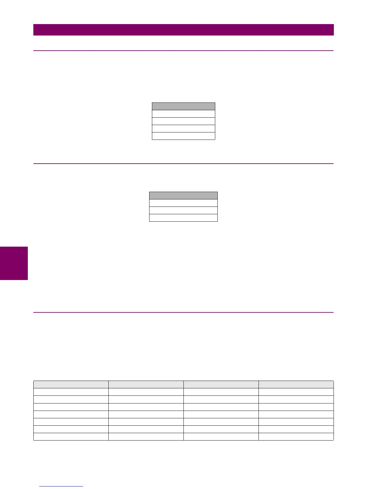
OPERATION BIT 1..24 These 24 bits are the outputs of each possible Operation modules, programmed in menu
Setpoint > Relay Configuration > Operations. The light up LED indicates their status 1
(activation)
Table 6–2: OPERATION BITS
6.2.2 BREAKER
The signals associated to the opened or closed status of the breaker can be monitored at “Actual > Status > Breaker”
Table 6–3: BREAKER STATUS
BREAKER OPEN: Open breaker status. In the switchgear selected as breaker, besides providing the usual
switchgear contact status, the system provides also the open breaker, closed breaker, and
undefined breaker states.
BREAKER CLOSED: Breaker closed.
BREAKER UNDEFINED: If there are two digital inputs configured for breaker contacts 52/a and 52/b, this status will be
present when both inputs are at 0 or at 1. This status can be caused by a wiring failure, failure of
auxiliary elements, etc.
6.2.3 PROTECTION
6.2.3.1 PROTECTION BLOCKS
(Actual > Status > Protection > Protection Blocks)
This screen shows the entire protection element blocks available. If the protection element is blocked, the green LED
located on the right side of the text will light up and will remain lit as long as the element remains blocked.
Protection elements block signals are configured at Setpoint > Relay Configuration > Protection Elements.
Table 6–4: PROTECTION ELEMENTS BLOCK
OPERATION BITS
OPERATION BIT 1
OPERATION BIT 2
…
OPERATION BIT 24
BREAKER STATUS
BREAKER OPEN
BREAKER CLOSED
BREAKER UNDEFINED
IOC BLOCK SIGNALS TOC BLOCK SIGNALS DIRECTIONAL BLOCKS VOLTAGE BLOCKS
PH IOC1 HIGH A /B / C BLK PH TOC1 HIGH A /B /C BLK PHASE DIR1 BLK INP PHASE UV1 BLOCK
PH IOC2 HIGH A /B / C BLK PH TOC2 HIGH A /B /C BLK PHASE DIR2 BLK INP PHASE UV2 BLOCK
PH IOC3 HIGH A /B / C BLK PH TOC3 HIGH A /B /C BLK PHASE DIR3 BLK INP PHASE UV3 BLOCK
PH IOC1 LOW A /B / C BLK PH TOC1 LOW A /B /C BLK NEUTRAL DIR1 BLK INP PHASE OV1 BLOCK
PH IOC2 LOW A /B / C BLK PH TOC2 LOW A /B /C BLK NEUTRAL DIR2 BLK INP PHASE OV2 BLOCK
PH IOC3 LOW A /B / C BLK PH TOC3 LOW A /B /C BLK NEUTRAL DIR3 BLK INP PHASE OV3 BLOCK
NEUTRAL IOC1 BLOCK NEUTRAL TOC1 BLOCK GROUND DIR1 BLK INP NEUTRAL OV1 HIGH BLK

 Loading...


