GE Multilin F650 Digital Bay Controller 5-121
5 SETPOINTS 5.8 RELAY CONFIGURATION
5
5.8.2 LEDS
F650 has 15 LEDs fully configurable from any logical variable, contact or virtual input. First 5
th
are latched by hardware, the
rest are self-reset but can be latched through PLC configuration.
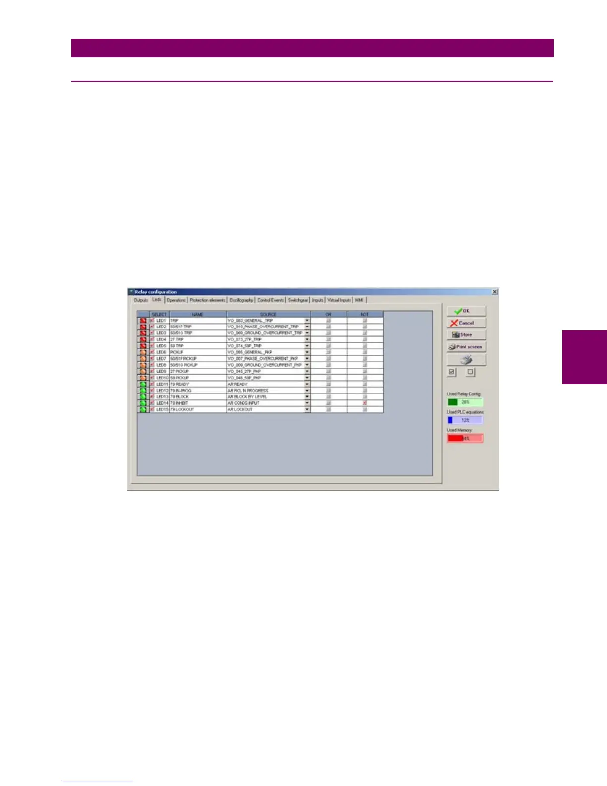
This window displays the entire relay LEDs with the following setpoint options for each of them:
• Select checkbox enables each LED. The LED must be enabled before modifying any other setpoint on that LED
• Name setpoint for defining identification for the LED
• Source setpoint defines which function; logic, remote input, digital input, etc. will activate the LED.
• OR checkbox for configuring the LED operation by activation of any of the indicated signals. The unit performs an OR
of the signals, and its output produces operation.
• NOT checkbox for inverting or not the configured logic.
From the LED configuration screen, it is possible to print the vertical LED label for the relay. For this purpose, press on the
printer icon. The label obtained will be similar to the default factory label, with black background and the LED texts in white.
This label can replace the original one under the black plastic cover. The label is also provided in word format and can be
modified by the user (e.g. different color marking)
Figure 5–41: LED CONFIGURATION

 Loading...


